Projects
Improving the Lab - Machining and Design
|
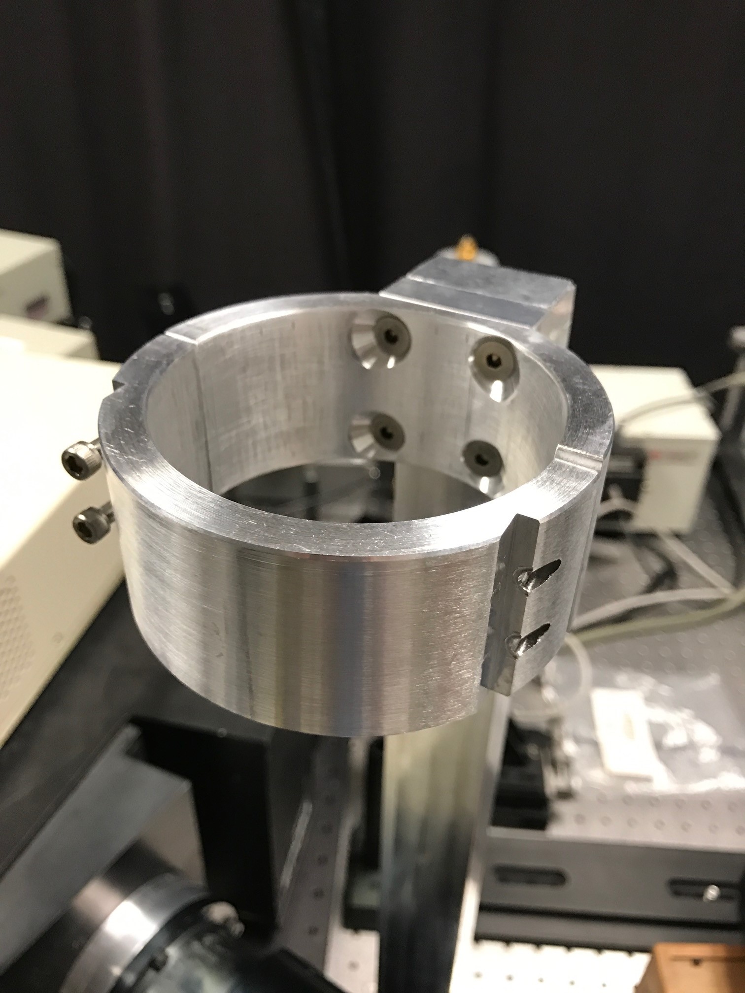
| A mount for a Ge detector |

|
| An indexing mirror mount |
Lab Automation

One of the common experiments done in the Photovoltaic Materials and Devices group is temperature dependent photoluminescence spectroscopy. A sample is placed in a cryostat, and excited with one of the many lasers available in the lab. The laser light excites electrons in the sample, promoting electrons to the conduction band of the material, and leaving "holes" in the valence band. These electrons and holes recombine after some time, and the resulting energy is emitted as a photon. This light that comes from the sample is the photoluminescence or PL. That light is sent through a filter to remove the excitation (laser) light, and then into a spectrometer so that the relative intensity of the light at each wavelength can be examined.
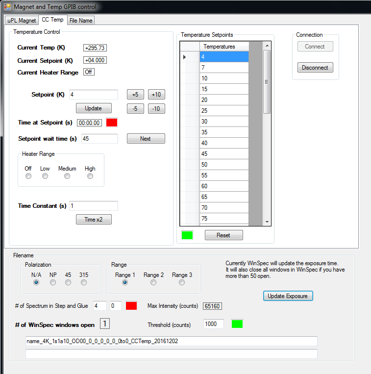
The photoluminescence system can be controlled completely from the computer. The Lakeshore 335 temperature controller is accessed via an Agilent GPIB to USB device, and the Acton spectrometer is controlled via USB and a program called WinSpec from Princeton Instruments. Originally, a user would have to manually change the temperature using some command, and then create some file name in the WinSpec program, and take a spectrum. I felt like since everything was being done on the computer, there should be a way to get the programs to talk to each other, and do a temperature scan automatically. Thus started my research into automating the WinSpec program.
I found an old manual for automating WinSpec using Visual Basic. I was fairly familiar with C# programming from doing some controller work in my undergraduate research, so I started making a small program using that. C# is fairly close to Visual Basic, so it didnt take much to figure out the commands that would work. At a certain point, it became clear that not all commands in WinSpec could be automated, and some of them (namely Step and Glue) I still needed to use. Thus I finished up my little program, and added some color boxes to act as flags. I then use a mouse macro program to run through my little program, and copy the appropriate filename into WinSpec. It can wait for a pixel color at certain points, and so I use the flags to control the macro progression somewhat. It still has a few bugs, but it has enabled me to take Temperature Dependent PL without having to babysit the system the entire time. It is very close to being able to take a full scan completely autonomously.
I have continued, and made many more programs to control
others parts of the lab. We can now do automatic Temperature Dependent
External Quantum Efficiency (EQE), Bias Dependent EQE, Temperature
Dependent Current-Voltage (JV), and Temperature Dependent
Electroluminescence (EL). Most of these are controlled by GPIB. We use
a Keithley 2400 sourcemeter for JV measurements and to control Bias. A
Standford Research 830 Lock-In amplifier is used for the
Electroluminescence and the EQE measurements. All of these programs
were created in Visual Studio using C#.NET.
CNC router
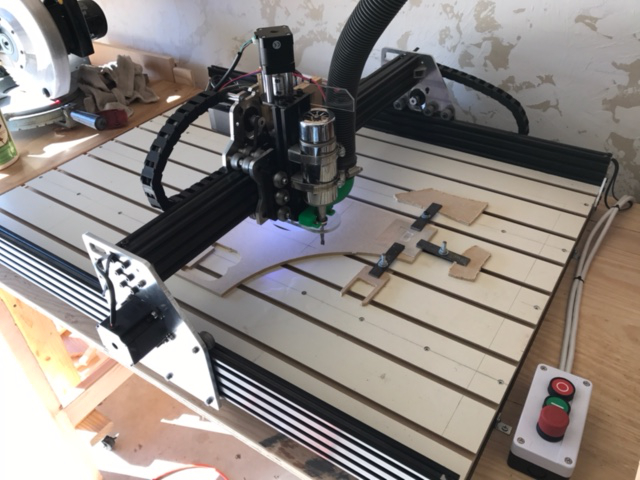
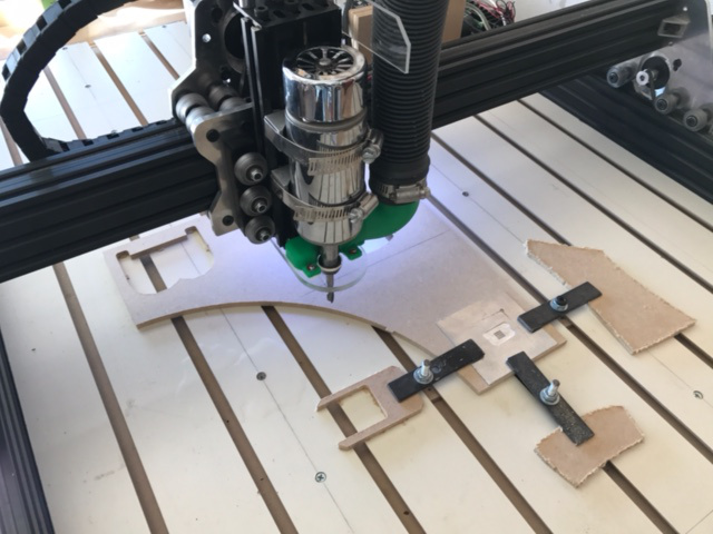
In March of 2016, my wife and I decided to purchase a small CNC router to do projects. I purchased a kit for an OX CNC from SMW3D. I then went through the instructions, and also followed some pointers in Dave Hyland's blog found here. I really liked his little jig for starting the tap straight in the ends of the aluminum extrusions, so I grabbed his .stl file and had the jig 3D printed at the OU IT store. That was the first thing that I have gotten 3D printed. The jig worked great, and many of Dave's pointers were very helpful.
In addition to the jig, I liked Dave's slatwall and t-nut approach for holding down material. I searched around on craigslist, and got some slatwall for cheap. I am still having some issues with keeping it perfectly flat, but overall it has been pretty good. Recently I used a pocket hole jig to screw the two pieces of slatwall together, and then used a 1" surfacing bit to plane the surface of the slatwall. While not as pretty, it is much more uniform now.
3D printing
Once I had 3D printed the jig for the CNC router mentioned above, I started work on my own files since 3D printing was now a cheap option. My second venture was to produce a vacuum inlet that would wrap around the CNC spindle, thus providing removal of chips and sawdust from the routing process. This required a interesting design, as the shape had to change from a circle (vacuum hose) to a horseshoe type shape around the spindle. I utilized the Swept and Stitch options in SolidEdge to smoothly join these two shapes.