Thevenin and Norton Equivalent Circuits:
The Simplest Picture of a Black Box Source
You are given a power supply in a black box with two terminals. There are two basic measurements you can make.
- The open circuit voltage, the voltage across the terminals when no current is being drawn. This is the highest voltage you can get from the power supply.
- The short circuit current, the current across the terminals when you short them with a wire. The ideal wire for this purpose will have zero resistance—thus the voltage across the terminals will be zero. This is the maximum current you can draw from the power supply.
(Actually you can get voltages and currents that exceed these values, but this can only happen if a power source is placed across its terminals.)
If you continued your measurements by placing different resistors between the terminals and then for each resistor, measured the current delivered by the supply and the voltage across the terminals and graphed your results, you would get a surprisingly simple answer.
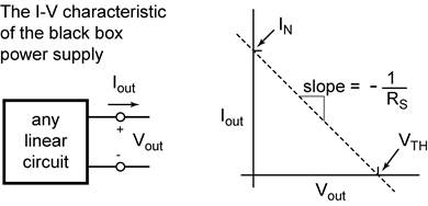
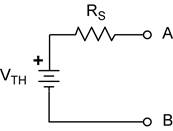
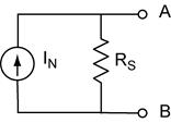
This simple behavior suggests that whatever is inside the black box can be replaced with a simple model. This is in fact the case. It turns out that there are two simple and equivalent models to describe a black box source. The Thevenin model: an ideal voltage source VTH in series with a resistor RS. The Norton model: an ideal current source IN in parallel with a resistor RN.
The following relationships for any two terminal network also apply:
RS = RTH = RN VTH = IN RS IN = VTH/RS
Note that the maximum power available from a network is transferred to a resistor loading that network when the load resistor is equal to RS.
Thevenin's Theorem: Any two terminals of a network of any number of resistors, current sources and/or voltage sources can be reduced to one voltage source in series with one resistor. The open-circuit voltage that appears across these two terminals is the Thevenin voltage. The Thevenin equivalent resistance is the resistance between these two terminals with all sources disabled (replaced by their equivalent resistances), as is done when applying superposition.
Procedure to find the Thevenin equivalent circuit.
- Locate the two “output” terminals.
- Remove anything from the terminals that is not to be considered part of the source.
- Find the open circuit voltage across these terminals. This is the Thevenin equivalent voltage, VTH.
- Now turn off all sources. Replace each source with its characteristic resistance. (Ideal voltage sources R = 0, a short circuit. Ideal current sources R = ∞, an open circuit.)
- Find the resistance across the terminals. This is the source resistance, RS.
Observations of the Thevenin equivalent circuit.
The output voltage is ![]() ; Note that when
; Note that when ![]() ;
; ![]()
The short circuit current is (![]() );
); ![]()
A plot of iout vs Vout is a straight line with a slope of −1/RS and a y intercept of IN.
![]()
This is exactly the behavior we found from the general black box power supply!
Norton's Theorem: Any two terminals of a network of any number of resistors, current sources and/or voltage sources can be reduced to one current source in parallel with one resistor. The short-circuit current available from these two terminals is the Norton current. The Norton equivalent resistance is the resistance between these two terminals with all sources disabled (replaced by their equivalent resistances) as is done when applying superposition.
Procedure to find the Norton equivalent circuit.
- Locate the two “output” terminals.
- Remove anything from the terminals that is not to be considered part of the source.
- Find the short circuit current between these terminals. This is the Norton equivalent current, IN.
- Now turn off all sources. Replace each source with its characteristic resistance. (Ideal voltage sources R = 0, a short circuit. Ideal current sources R = ∞, an open circuit.)
- Find the resistance across the terminals. This is the source resistance, RS.
Observations of the Norton equivalent circuit.
The output voltage is ![]() ; Note that when
; Note that when ![]() ;
; ![]()
The short circuit current is (![]() );
); ![]()
A plot of iout vs Vout is a straight line with a slope of −1/RS and a y intercept of IN.
![]()
This is exactly the behavior we found from the general black box power supply!
Thevenin-Norton Source Transformation.
These quantities obey the Ohm’s Law relationship: ![]() . Thus if any two
quantities are know the third can be determined.
. Thus if any two
quantities are know the third can be determined.
Example: You have already determined the Thevenin
equivalent circuit, you know VTH and RS. The
Norton equivalent circuit has the same RS and the Norton
current is ![]() .
.
Example: You have determined both the open circuit
voltage VTH and the short circuit current IN.
The source resistance (for both Thevenin and Norton) is ![]()
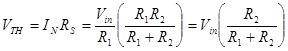
Example: Find the Thevenin equivalent of a voltage divider.
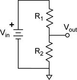
So far we have looked at circuits which have a voltage or current source explicitly included. The voltage divider is an example of a circuit were the voltage source is implied and not drawn in the schematic. The circuit on the left is the standard way to represent the voltage divider. The schematic on the right is what is implied.
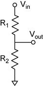
The output of the voltage divider is always measured with zero current flowing through Vout. That is, Vout is the open circuit voltage which is VTH.
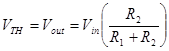
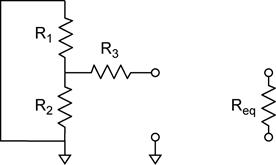
The source resistance RS is then the equivalent resistance REQ seen across the output terminals with the voltage source turned off. The output terminal labeled Vout is obvious; the second terminal is the point where Vout is referenced. Here the second terminal is ground.
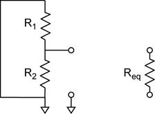
In this example R1 and R2 are then in parallel.
![]()
The Norton equivalent current is then:

We could also find the Norton equivalent current by calculating the short circuit current of the voltage divider. The short circuit current is obtained by shorting the output of the voltage divider (left).
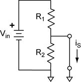
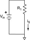
Notice that this effectively removes R2 from the circuit. The short circuit current is then obtained using Ohm’s law, which is the same result we obtained above.
![]()
We can now find VTH from IN:
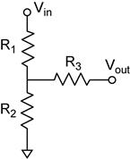
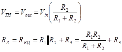
Example: Find the Thevenin equivalent of a voltage divider with a series resistor.
In this example the open circuit voltage is the same as the simple voltage divider because no current is flowing through R3. The source resistance RS is affected by R3 (right).