Notes on Diodes and Rectifiers.
Definitions.
What is the difference between the diode and the rectifier? As nouns, the terms diode and rectifier are almost interchangeable. They are both devices that allow current to flow only in one direction. The term diode is usually used for devices rated less than 0.5 A. The term rectifier is usually used for devices rated greater than 0.5 A. The distinction between diode and rectifier has nothing whatsoever to do with any difference in the construction or with any difference in the physics of how they work.
Rectify is also a verb, “The AC current was rectified to make DC current.”
Rectification is the process. “The signal rectification circuit used a silicon diode.”
EXECUTIVE SUMMARY:
DIODES.
![]()
diode ON: Vac = Vf (forward conduction) definition: Vac = Vanode cathode
diode OFF: Vac < Vf (I = 0)
- Conduct only when the forward bias exceeds the forward voltage drop of the diode. They do not conduct when reverse biased.
- For voltage drop calculations, the current is zero if the bias is reverse or if the bias is forward and less than the forward voltage drop Vf. If the diode is in forward conduction, the resistance is zero and the forward voltage drop is constant (Vf).
ZENER DIODES.
![]()
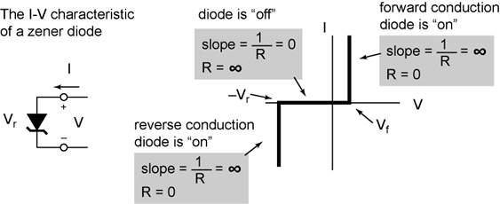
zener diode ON: Vac = Vf (forward conduction)
Vac = −Vr (reverse conduction)
zener diode OFF: −Vr < Vac < Vf (I = 0)
- Conduct in two different bias regions. 1) Zener diodes exhibit normal diode behavior, they conduct when the forward bias exceeds the forward voltage drop of the diode. 2) They conduct in the reverse direction when the reverse bias exceeds the zener breakdown voltage.
- For voltage drop calculations, the current is zero if the bias is reverse and less than the zener voltage, Vr, or if the bias is forward and less than the forward voltage drop, Vf. If the diode is in forward conduction, the resistance is zero and the forward voltage drop is constant Vf. If the diode is in reverse conduction, the resistance is zero and the reverse voltage drop is constant (Vr).
Diodes (normal diodes)
Diodes allow current to flow only in the forward direction. The forward direction is shown in the schematic by the direction of the triangle. Semiconductor diodes are formed by a pn junction. The most common type of semiconductor diode is the silicon diode. Semiconductor pn junction diodes can be formed from materials other than silicon, such as germanium, selenium, and a host of semiconductor materials used in light emitting diodes (LEDs). (The electrical characteristics of LEDs are the same as normal diodes.)
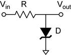
Schematic symbol
![]()
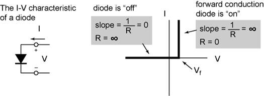
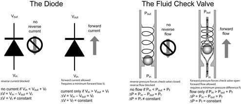
Forward biased (Vanode > Vcathode). The diode is said to be forward biased when the anode is more positive than the cathode. The ideal diode will have zero resistance when forward biased, however real diodes require that the forward bias exceed a threshold voltage Vf before forward conduction begins. When the diode is in forward conduction, the voltage drop across the diode is constant. The forward voltage drop is an intrinsic property of the semiconductor material used to make the pn junction and is related to the band gap. Thus Vf is the same for all silicon diodes.
Reverse biased (Vanode < Vcathode). The diode is said to be reverse biased when the anode is more negative than the cathode. The ideal diode will have infinite resistance when reverse biased. Real diodes do have some leakage current when reverse biased. We will not need to worry about the leakage current in this class.
If the reverse bias is great enough, the electric field within the pn junction will cause the diode to begin to conduct in the reverse direction! This reverse breakdown (called zener breakdown) occurs very sharply. The large amount of current that will then flow could destroy the diode. Special types of diodes called zener diodes are designed to operate in the zener breakdown region. Normal diodes would be destroyed. A feature of the zener breakdown is that the breakdown itself is determined by the electric field in the junction. The relationship between the zener break down voltage and the electric field in the junction is determined by the thickness of the pn junction. Thus the zener voltage is not an intrinsic property, but can be engineered to occur from a few volts to hundreds of volts.
Practical information:
Peak Reverse Voltage This is the maximum reverse operating voltage. Higher voltages may cause the diode to breakdown.
Current. This is the maximum current the diode is rated to conduct. Greater currents may destroy it.
Forward Voltage Drop is the voltage drop across the diode when it is forward conduction. For silicon diodes Vf = 0.6 V.
Zener Diodes
Zener diodes have all the same characteristics of normal diodes. The difference is that they are designed to operate in the reverse (zener) breakdown region. The only zener diodes you are likely to encounter are silicon.
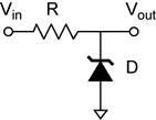
Schematic symbol
![]()
Practical information:
Zener Voltage. This is the reverse breakdown voltage −Vr. This is the defining specification, Vr is typically written on the schematic like any other component value.
Current. This is the maximum current the diode is rated to conduct. Greater currents may destroy it.
Forward Voltage Drop is the voltage drop across the diode when it is forward conduction. For silicon diodes Vf = 0.6 V. ZENER DIODES CONDUCT IN THE FORWARD DIRECTION AND HAVE THE SAME FORWARD VOLTAGE DROP AS OTHER SILICON DIODES.
Counting Diode (Voltage) Drops
(Note: You will get a diode drop for each direction of current.)
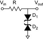
Consider diodes in series between node a and node b.
S1) Follow the path from a to b.
A) If there are any regular (non-zener) diodes pointing against the current. No current will flow in that direction; one would simply say no conduction (infinite voltage drop).
B) If no regular diode opposes the current, count the number of diodes in forward conduction and the number of zener diodes in reverse conduction. The voltage drop DUE TO THE DIODES for current flowing from a→b is the sum of these individual voltage drops. If any resistors are also in series between a and b, they will contribute their iR drop to the total voltage drop between a and b, but not to the total diode drop. The diode drop represents the minimum Vab required to get current to flow.
S2) The total diode drop between b and a is found by reversing the direction of current and repeating the process.
Consider diodes in parallel between node a and node b.
P1) Determine the total diode drop for each parallel leg of the circuit between a and b. The total diode drop for each leg can be found using the procedure for series case described above. The diode drop for the parallel combination is determined by (equal to that of) the leg with the smallest diode drop.
P2) The total diode drop for each parallel leg of the circuit between b and a is found by reversing the direction of current and repeating the process.
Power Dissipation in Diodes
When a diode is conducting, power is dissipated (lost) in the diode because there is both a voltage drop across it and a current through it.
diode ON: forward conduction: P = IVf (Note Vf is a constant!)
reverse conduction: P = IVr (Zener ONLY!!! Note Vr is a constant!)
diode OFF: P = 0 (I = 0)
Diodes are nonlinear devices: V/I ≠ constant! For diodes, resistance not constant, it is a dynamic property. Thus we cannot use Ohm’s Law to define the power in terms of current and resistance or voltage and resistance as we did for resistors!!
The Check Valve Analogy. An excellent analogy of how rectifiers work is the fluid check valve. In fluids the analogy of voltage is the pressure and of current is the flow rate.
Hint: How to count diode drops in a circuit.
For example, you could be ask to count diode drops between two points in the circuit, or between one point and common (ground). To do this you will need to count the number of diodes along the DC path between these two points.
- The diodes along this path MUST be pointed in the same direction on the path, so that a DC current could flow along the path.
- The path cannot go through a capacitor, because capacitors block DC current, thus would not be a DC path.
- The direction of the path with respect to the diodes is not important. Tracing a path opposite to the direction of the diodes simply means the current would flow in the opposite direction, but this is still a valid DC path.
- Note that the DC path may flow through the common. All points connected to common are in fact connected together. Common is a single node!
Diode drops with two or more parallel paths
· If there is more than one DC path, with the diodes pointed the same direction (current flowing the same direction between the two nodes), the number of diodes drops equal to the smallest number. If one of the DC paths has no diodes, the number of diode drops is zero.
· It is possible to have a different DC path for each direction of current. In this case you can have a different diode drop for each direction of current flow.
Current flow in parallel paths containing diodes.
· For very small currents, the voltage drop across resistors can be ignored in comparison to the voltage drop across the diodes. The current will flow through the path with the smallest diode drop.
· If there are resistors in the path, increasing current will increase the voltage drop across the resistors. The total voltage drop along that path will be the sum of the voltage drops in the resistors and the diode drops. Under this condition, additional current may flow through parallel paths with higher diode drops. The details depend on the circuit.
Diode Circuit applications.
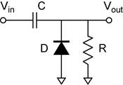
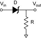
Clamp
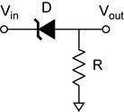
Level Shifters
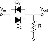
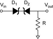
Clipper

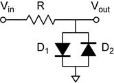
Clipper (continued)
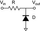
Peak detector
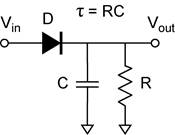
Power Supply Applications
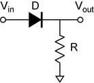
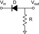
Half-Wave Rectifier (R is the load.)


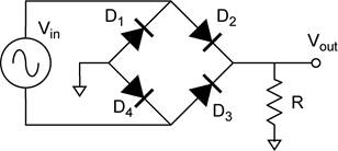
Full-Wave Rectifier using a Bridge Rectifier. (R is the load.)
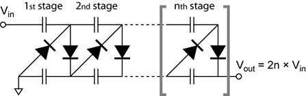
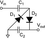
Half-Wave Voltage Doubler. (R is the load.)
Full-Wave Voltage Doubler
Full-Wave Voltage Quadrupler
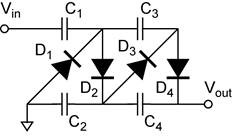
General 2n Voltage Multiplier