Notes on Capacitors, Inductors, and on RC and RL Transients.


Capacitors

Capacitors store electrical energy (electric charge on metal plates). The current through a capacitor is proportional to the rate of change of the voltage across the capacitor.

Schematic symbol(s)

polarized_C

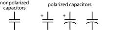
Capacitance is the proportionality between charge and potential (voltage).

Capacitance is also the dynamic relationship between the current flowing through the capacitor (rate of change of charge) and the rate of change of the voltage.
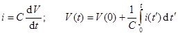
             Recall that:  

Units:  The unit of capacitance is the farad.

   (A farad is a coulomb per volt and an ampere-second per volt.)


Practical information:  

Capacitance. The farad is a large unit. Typical capacitance values are measured in microfarads (μF = 10−6 F), nanofarads (nF = 10−9 F), and picofarads (pF = 10−12 F).

Voltage (working voltage) Capacitors are rated for the maximum working voltage. Voltages higher than this may damage the capacitor irreversibly.

Polarization. Some types of capacitors are polarized. The capacitor needs to be connected to the circuit in the correct polarity. Reversing the polarity can damage the capacitor. Often the capacitance is dramatically different if the polarity is incorrect; some even look more like resistors!

Types of dielectric. The type of dielectric (insulator) between the plates determines the detailed electrical characteristics of the capacitor, such as leakage, physical size, and high frequency performance. In this class we will not be concerned with these details. It is however necessary to understand that these details are responsible for the wide variety of shapes, sizes, colors, and types of capacitors.


Capacitors in parallel:  The equivalent capacitance of capacitors in parallel is the sum of the capacitances of all of the capacitors.
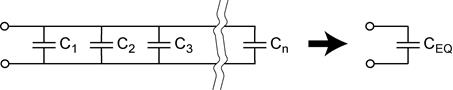
parallel_C

Capacitors in parallel: 

Discussion:  What quantity is the same for a circuit with capacitors in parallel?
Capacitors in series:
  The equivalent capacitance of capacitors in series is the reciprocal of the sum of the reciprocals of the capacitances of all of the series capacitors.
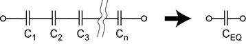
series_C

Capacitors in series: 

Discussion:  What quantity is the same for a circuit with capacitors in series?
Inductors

Inductors store magnetic energy (magnetic field of a coil). The voltage across an inductor is proportional to the rate of change of the current through the inductor.

Schematic symbol(s)

schematic_L

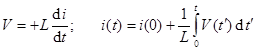
Inductance is the proportionality between the voltage across an inductor and the rate of change of the current through it.

The unit of inductance is the henry.

   (A henry is a volt-second per ampere.)

Practical information:  

Inductance. Typical inductance values are measured in henries (H), millihenries (mH = 10−3 H) and microhenries (μH = 10−6 H).

Series resistance. The ideal inductor has zero resistance, however real inductors are made from many turns of wire. The resistance of the wire is often significant and can be included in the circuit model as a resistor in series with the inductor.

Core materials. The inductance of a coil can be greatly increased by placing a magnetic material inside the coil. The type of magnetic material inside the coil determines the detailed electrical characteristics of the inductor, such as eddy current losses and high frequency performance. In this class we will not be concerned with these details. It is however necessary to understand that these details are responsible for the wide variety of types of inductors.

Inductors in parallel:  The equivalent inductance of inductors in parallel is the reciprocal of the sum of the reciprocals of the inductances of all of the parallel inductors.
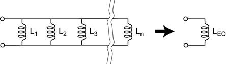
parallel_L

Inductors in parallel: 

Discussion:  What quantity is the same for a circuit with inductors in parallel?

Inductors in series:  The equivalent inductance of inductors in series is the sum of the inductances of all of the inductors.
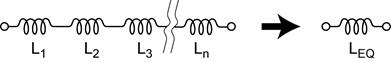
series_L

Inductors in series: 

Discussion:  What quantity is the same for a circuit with inductors in parallel?
Summary:  Resistors, Capacitors, and Inductors


Summary


resistors

capacitors

inductors

series

parallel

stored energy

0

DC steady state


no current through C


no voltage drop across L

transient

time constant


continuous variable


V

i


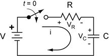
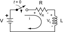
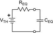
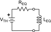
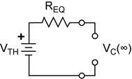
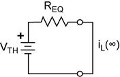
First-Order Transient Response in RC and in RL Circuits.
These two circuits illustrate the basic first-order RC and RL circuits.


RC EXAMPLE

RC_ex1b

Before the switch is closed. VC = 0 and i = 0. Because capacitors can store electrical energy, the capacitor could have an initial voltage that is not zero. Clearly no current can flow before the switch is closed. From KVL we note that the voltage across the switch is V.

The initial state (immediately after the switch is closed). A current will begin to flow to charge C. At the instant after the switch is closed, (t = 0+) VC=0 so all of the voltage drop appears across R. Thus the initial charging current is i = V/R. (To determine the initial state, C is modeled as a voltage source.)


The final state (DC steady state).
After the switch has been closed for a long time, the capacitor is completely charged (VC = V) and the current has decayed to zero (i = 0). In this limit C is modeled as an open circuit.

The continuous variable. Capacitors store energy. Because the stored energy cannot be changed instantaneously, change requires time. For capacitors, VC is the circuit variable directly related to the stored electrical energy. This means that the voltage across the capacitor the instant before the switch is closed and the instant after the switch is closed are the same, VC(t=0−) = VC(t=0+).

The transient response. The transient response is the description of how the system evolves from the initial to the final state. We can write a differential equation from KVL, substituting, and then differentiating and dividing by R. The system evolves from the initial to the final state with a characteristic time constant.


RL EXAMPLE

RL_ex1b

Before the switch is closed. VL = 0 and i = 0. Although inductors can store magnetic energy, this requires a flow of current through the inductor. Clearly no current is flowing before the switch is closed. From KVL we note that the voltage across the switch is V.

The initial state (immediately after the switch is closed). The current will begin to change, however the inductor opposes the change in current. At the instant after the switch is closed, (t = 0+) the current must still be zero, i = 0 so all of the voltage drop appears across L. Thus the initial VL = V (To determine the initial state, L is modeled as a current source.)

The final state (DC steady state). After the switch has been closed for a long time, VL has decayed to zero (VL = 0) and the current is constant (i = V/R). In this limit L is modeled as a short circuit.

The continuous variable. Inductors store energy. Because the stored energy cannot be changed instantaneously, change requires time. For inductors, iL is the circuit variable directly related to the stored magnetic energy. This means that the current through the inductor the instant before the switch is closed and the instant after the switch is closed are the same, iL(t=0−) = iL(t=0+).

The transient response. The transient response is the description of how the system evolves from the initial to the final state. We can write a differential equation from KVL, substituting, and then rearranging and dividing by R. The system evolves from the initial to the final state with a characteristic time constant.


Simple method for first-order transients in RC and RL circuits.

Most RC and RL circuits you will encounter are simple first order systems. This means that they have only one C or one L, or that they can be reduced to a circuit that does. The solution will have the following form.

Our task is to identify the required parameters.

All first order circuits can be characterized by three quantities:

1)   The time constant τ. The characteristic time in which the system evolves.

2)   The initial state x(0). The state of the system the instant after the transient.

3)   The final state x(∞). The state that the system is evolving to and would eventually reach if not disturbed.

Step 1. Determine the time constant. For the conditions immediately after the transient, write the equivalent circuit in the following form. The procedure is identical to determining the Thevenin and Norton equivalent circuits. Only the source resistance REQ is necessary to determine the time constant. The time constant is then  or

RC_ex2 RL_ex2

Step 2. Find the initial state. We start with the quantities known to be continuous across the transient (from t = 0− to t = 0+, for example). For capacitors VC is continuous and for inductors iL is continuous. Analysis at the instant that the transient begins is carried out by replacing C with a voltage source with VC and replacing L with a current source with iL. NOTE:  This analysis is only valid for the initial instant of the transient!

RC_ex2bRL_ex2b

Step 3. Find the final state. This is the state of the system long after the transient has died away. Analysis of the final state is carried out by replacing C with an open circuit and L with a short circuit.

RC_ex2cRL_ex2c

Step 4. Substitute into the values into the equation.

This is the full solution that describes how VC and iL evolve after the transient

Creative Commons License
This work by L.A. Bumm is licensed under a Creative Commons Attribution-NonCommercial-ShareAlike 4.0 International License.