Notes on Operational Amplifiers (Op Amps).
Comments. The name Op Amp comes from “operational amplifier.”
Op Amp Golden Rules (memorize these rules)
1) The op amp has infinite open-loop gain.
2) The input impedance of the +/− inputs is infinite. (The inputs are ideal voltmeters). The output impedance is zero. (The output is an ideal voltage source.)
3) No current flows into the +/− inputs of the op amp. This is really a restatement of golden rule 2.
4) In a circuit with negative feedback, the output of the op amp will try to adjust its output so that the voltage difference between the + and − inputs is zero (V+ = V−).
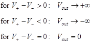
Ideal Op Amp Behavoir.
The relationship between the input and the output of an ideal op amp (assumptions: infinite open loop gain, unlimited voltage).
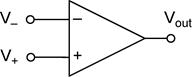
Op Amp Schematic Symbol (The upper input is usually the inverting input. Occasionally it is drawn with the non-inverting input on top when it makes the schematic easier to read. The position of the inputs may vary within the same schematic, so always look closely at the schematic! )
Negative Feedback. Most of the basic op amp building blocks rely on negative feedback. You can easily identify the type of feedback used by the op amp circuit. For negative feedback, the output is connected to the inverting input (− input). For positive feedback, the output is connected to the non-inverting input (+ input).
The Input
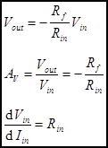
Impedance of the Circuit is defined as the rate of change of Vin
with respect to a change of Iin. This is simply the derivative![]() . The input impedance of the circuit
is not in general the same as the impedance of the op amp’s inputs.
. The input impedance of the circuit
is not in general the same as the impedance of the op amp’s inputs.
The Output
Impedance of the Circuit, for the examples shown here, is the output
impedance of the op amp. Output impedance is defined as the rate of change of Vout
with respect to a change of Iout. This is simply the
derivative![]() . For the ideal op amp, the
output impedance is zero.
. For the ideal op amp, the
output impedance is zero.
Basic Op Amp Building Blocks
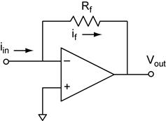
Inverting Amplifier
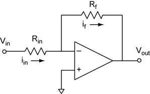
Analysis of
the inverting amplifier starts with our op amp golden rules. From rule #4 we
know that ![]() and that V− =
0 because V+ is connected to ground. From rule #3 we know
that
and that V− =
0 because V+ is connected to ground. From rule #3 we know
that ![]() because no current flows into
the inverting input.
because no current flows into
the inverting input.
![]()
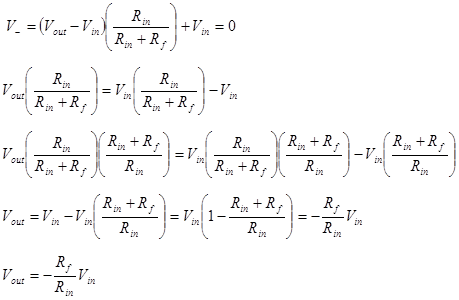
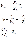
Then we can find the relationship between Vin and Vout using Ohm’s law (OL) and Kirchhoff’s voltage law (KVL).
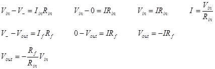
The voltage gain AV is the derivative of Vout with respect to Vin. When the amplifier has only one input and Vout = 0 when Vin = 0, we will make the assumption that AV = Vout/Vin.
![]()
Alternatively we could have started our analysis from the voltage divider formed by Rf and Rin. The voltage divider will relate the voltage at V− with Vout and Vin. In this case the total voltage across the divider is Vout − Vin. Because the bottom end of the divider is not connected to ground, we must add the extra Vin term to offset V−. We arrive at the same result.
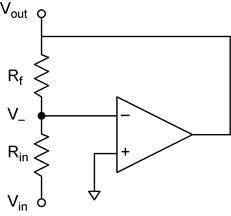
The input impedance of the inverting amplifier is determined by Rin. Note that V− is held at the same voltage as V+ by the op amp feedback. Because V+ is connected to ground, the input impedance is just Rin.
Non-inverting Amplifier
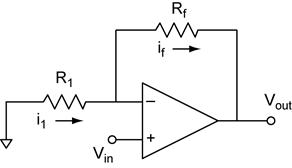
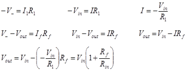
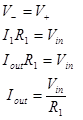
Analysis of
the non-inverting amplifier starts with our op amp golden rules. From rule #4
we know that ![]() and that V− =
Vin because V+ is connected to Vin.
From rule #3 we know that
and that V− =
Vin because V+ is connected to Vin.
From rule #3 we know that ![]() because no
current flows into the inverting input.
because no
current flows into the inverting input.
![]()
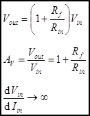
Then we can find the relationship between Vin and Vout using Ohm’s law (OL) and Kirchhoff’s voltage law (KVL).
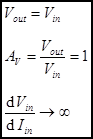
The voltage gain AV is the derivative of Vout with respect to Vin. When the amplifier has only one input and Vout = 0 when Vin = 0, we will make the assumption that AV = Vout/Vin.

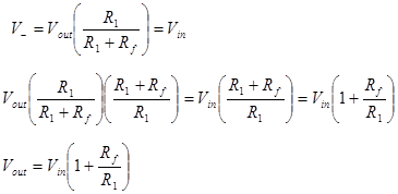
Alternatively we could have started our analysis from the voltage divider formed by Rf and Rin. The voltage divider will relate the voltage at V− with Vout and Vin. In this case The total voltage across the divider is Vout and the we know that V− = Vin. We arrive at the same result.
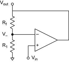
The input impedance of the non-inverting amplifier is the input impedance of the op amps input. For an ideal op amp the input impedance is infinite.
Voltage Follower
This is a
special case of the non-inverting amplifier with Rin → ∞ and Rf
= 0. The follower has a very high input impedance. Voltage follower has
application when the source voltage can not supply very much current, a pH
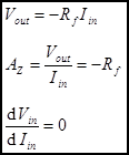
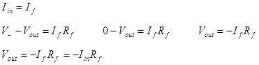
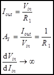
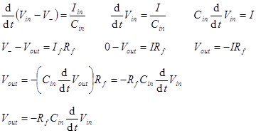
meter for example. Current-to-Voltage Converter (AKA, I-V Converter, Transimpedance
Amplifier). This circuit takes an input current and converts it to an output
voltage. The input impedance of the ideal current to voltage converter is zero
(the ideal current meter). Analysis of
the current-to-voltage converter starts with our op amp golden rules. From rule
#4 we know that Then we can
find the relationship between Vin and Vout
using Ohm’s law (OL) and Kirchhoff’s voltage law (KVL). The
current-to-voltage converter has transimpedance gain. Transimpedance gain is
not unitless, it has units of impedance (Ohms). The units can also be expressed
as V/A (volts/ampere), which is often a more useful way to think of the
gain—the output voltage per input ampere. The transimpedance gain AZ
is the derivative of Vout with respect to Iin.
When the amplifier has only one input and Vout = 0 when Iin = 0,
we will make the assumption that AV = Vout/Iin. Voltage-to-Current Converter (AKA, V-I Converter, Transadmittance
Amplifier). This circuit takes an input voltage and converts it to an output
current. The input impedance of the voltage-to-current converter is the input
impedance of the op amps input. For an ideal op amp the input impedance is
infinite. The schematic looks strange at first because there is no output
terminal! However the output is the current flowing through the load. Analysis of
the voltage-to-current converter starts with our op amp golden rules. From rule
#4 we know that Then we can
find the relationship between Vin and Iout. The
current-to-voltage converter has transadmittance gain. Transadmittance gain is
not unitless, it has units of admittance (Siemens, AKA Ohm–1). The
units can also be expressed as A/V (amperes/volt), which is often a more useful
way to think of the gain—the output current per input volt. The transadmittance
gain AY is the derivative of Iout with
respect to Vin. When the amplifier has only one input and Iout
= 0 when Vin = 0, we will make the assumption that AY
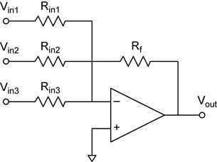
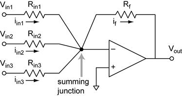
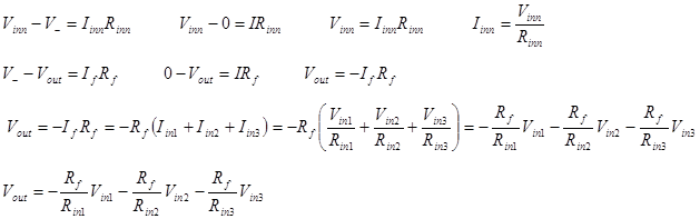
= Iout/Vin. Summing Amplifier. This circuit will add
(and subtract) the input voltages. Subtraction is accomplished by inverting the
voltages before adding them. Note that summing can only occur for inputs to the
inverting side of the op amp. This is because of the V− node
is a current summing junction where the input currents sum to the feedback
current.
This is
another look at the summing amplifier that emphases the summing junction. Analysis of
the summing amplifier starts with our op amp golden rules. From rule #4 we know
that Then we can
find the relationship between Vin and Vout
using Ohm’s law (OL) and Kirchhoff’s voltage law (KVL). The voltage gain AV
is the derivative of Vout with respect to Vin.
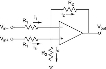
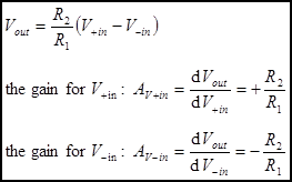
Differential Amplifier. The term differential is used in the
sense of difference. Do not confuse the differential amplifier with the
differentiator. One important application of the differential amplifier overcomes
the problem of grounding that you encountered in lab when using the
oscilloscope to make measurements. The typical oscilloscope always performs
voltage measurements with respect to is own ground. A differential amplifier
used before the scope input could measure the V+in with
respect to V−in. The ground of the differential amplifier
would be connected to the ground of the scope for this application, so the Vout
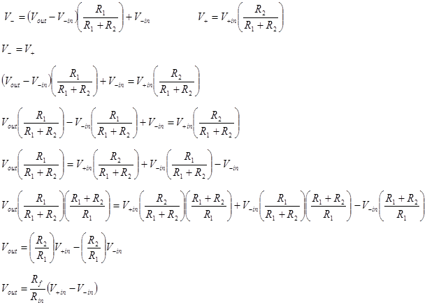
will be measured correctly. Analysis of
the differential amplifier starts with our op amp golden rules. From rule #4 we
know that Then we can
find the relationship between V+in, V−in,
and Vout using the voltage divider equations. We recognize
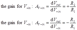
that The voltage gain AV
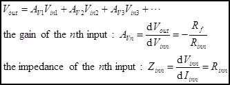
is the derivative of Vout with respect to each input Vin.
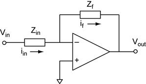
The inverting amplifier with generalized impedances.
The results derived above can be extended to general impedances. Note that Zf
and Zin can be the impedance of any network. The following
are examples of the inverting amplifier, but ANY of the previous examples can
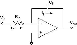
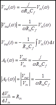
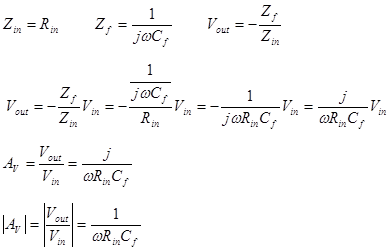
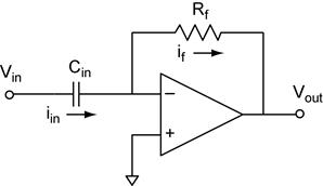
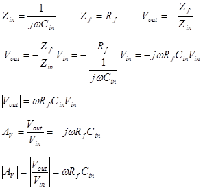
be generalized in this way. Integrator. A capacitor as the feedback
impedance. Analysis of
the integrator in the frequency domain is a simple extension of our generalized
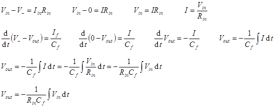
result for the inverting amplifier. Time
Domain Analysis of the Integrator starts with our op amp golden rules. From
rule #4 we know that Then we can
find the relationship between Vin and Vout
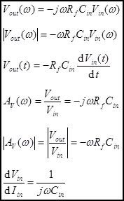
using Ohm’s law (OL) and Kirchhoff’s voltage law (KVL). Differentiator. A
capacitor as the input impedance. Analysis of
the differentiator in the frequency domain is a simple extension of our
generalized result for the inverting amplifier. Time
Domain Analysis of the Differentiator starts with our op amp golden rules. From
rule #4 we know that Then we can
find the relationship between Vin and Vout
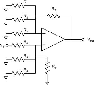
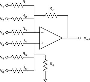
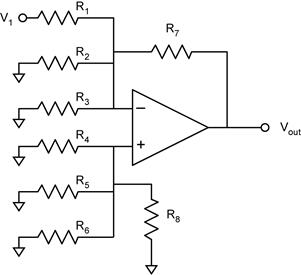
using Ohm’s law (OL) and Kirchhoff’s voltage law (KVL). The General Op Amp Circuit Example:
an op amp circuit with 3 inverting and 3 non-inverting inputs What can we
say about such a complicated looking amplifier? Don’t panic, we can use what we
have learned from the above analyses to painlessly arrive at the solution. Without
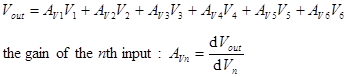
doing any analysis, what can we say? First, we know that Second, we
know that the voltage gains for V1, V2, and
V3 will be inverting (negative) and that the voltage gains
for V4, V5, and V6 will
be non-inverting (positive). We could simply blaze away at the problem by
applying the op amp golden rules just like we did for the derivations for the
basic op amp building blocks, but there is a better way. The Strategy. We will make
use of the results for the basic op amp building blocks and the principle of
superposition (e.g. the inverting amplifier and the non-inverting amplifier). To
apply the principle of super position, we analyze the gain for one input at a
time and turn off all the other inputs (set them to zero). We treat each
input as an ideal voltage source, so that an input that is turned off
is equivalent to a connecting the input terminal directly to ground. The
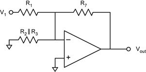
inverting inputs and the non-inverting inputs will behave differently. Analysis of the Inverting
Inputs by Superposition Let’s first
use analyze the voltage gain AV1 of the input V1.
We proceed by connecting all the other inputs to ground. (Analysis of the
voltage gain for the other inverting inputs (Av2 and Av3)
is analogous.) This simplifies to: Notice that
the non-inverting input, V+ is connected to ground though a
resistor. Because no current flows into the op amp’s inputs, V+
= 0, equivalent to it being connected directly to ground (see below). This looks
like a summing amplifier with V2 = V3 = 0. The
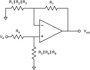
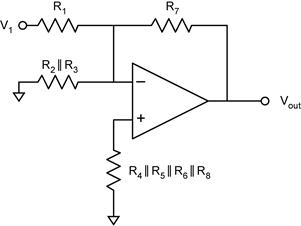
result for the summing amplifier is Analysis of the Non-Inverting
Inputs by Superposition Now let’s analyze
the voltage gain AV4 of the non-inverting input V4.
We proceed by connecting all the other inputs to ground. (Analysis of the
voltage gain for the other non-inverting inputs (Av5 and Av6)
is analogous.) This simplifies to: This is a
non-inverting amplifier. The resistors on the non-inverting side, R4,
R5, R6, and R8, form a
voltage divider that reduces the voltage seen by V+. It is
the voltage at V+ that is seen by the op amp. The voltage gain
of V+ is determined by the resistors on the inverting side, R1,
R2, R3, and R7. Hence the
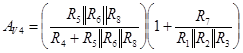
voltage gain AV4 of the V4 input has a term
from the voltage divider, relating V4 to V+,
and a term for the voltage gain of V+, relating V+
to Vout. The voltage gain AV4 is the
product of the two term and relates V4 to Vout. The voltage
gains for the other non-inverting inputs can be found in this way. An
important observation is that multiple inputs into the non-inverting side
of the op amp do not sum in the simple way that they do for inverting inputs. Thus
the summing amplifier that we listed as a basic building block does not have a
non-inverting analog! (If we need a non-inverted sum, we just follow the
summing amplifier with a unity gain inverting amplifier.)
![]() and that V−
= 0 because V+ is connected to ground. From rule #3 we know
that
and that V−
= 0 because V+ is connected to ground. From rule #3 we know
that ![]() because no current flows into
the inverting input.
because no current flows into
the inverting input.![]()
![]()
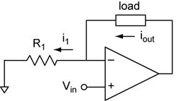
![]() and that V+
= Vin and V– = I1R1
(OL). From rule #3 we know that
and that V+
= Vin and V– = I1R1
(OL). From rule #3 we know that ![]() because
no current flows into the inverting input.
because
no current flows into the inverting input.![]()
![]()
![]() and that V− =
0 because V+ is connected to ground. From rule #3 we know
that
and that V− =
0 because V+ is connected to ground. From rule #3 we know
that ![]() because no current flows into
the inverting input. (Iinn is the current of the nth
input.)
because no current flows into
the inverting input. (Iinn is the current of the nth
input.)![]()
![]() . From rule #3 we know that
. From rule #3 we know that ![]() and that
and that ![]() because no current flows into
the inputs.
because no current flows into
the inputs.![]()
![]() and that V+
will be the output of the voltage divider formed by the two resistors connected
to the non-inverting input. The voltage at V− is the output
of the voltage divider formed by the two resistors connected to the inverting
input.
and that V+
will be the output of the voltage divider formed by the two resistors connected
to the non-inverting input. The voltage at V− is the output
of the voltage divider formed by the two resistors connected to the inverting
input.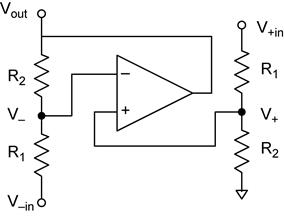
![]() and that V−
= 0 because V+ is connected to ground. From rule #3 we know
that
and that V−
= 0 because V+ is connected to ground. From rule #3 we know
that ![]() because no current flows into
the inverting input.
because no current flows into
the inverting input.![]()
![]() and that V−
= 0 because V+ is connected to ground. From rule #3 we know
that
and that V−
= 0 because V+ is connected to ground. From rule #3 we know
that ![]() because no current flows into
the inverting input.
because no current flows into
the inverting input.![]()
![]() . We can do
the same analysis for each inverting input. (Why don’t the two resistors R2
and R3 enter this analysis for AV1? Hint: Consider
the voltage across these two resistors.)
. We can do
the same analysis for each inverting input. (Why don’t the two resistors R2
and R3 enter this analysis for AV1? Hint: Consider
the voltage across these two resistors.)