Introduction to Electronics: Start Here
Basic Quantities
Voltage (symbol V) is the measure of electrical potential difference. It is measured in units of Volts, abbreviated V. The example below shows several ways that voltages are specified.
Voltage is always measured between two points. One point is taken as the reference. We can explicitly state this using subscripts. Vab is the voltage at node a with respect to b. The choice of reference node, a or b, determines the polarity (sign) of the voltage. Thus the order of the subscripts determines the sign of the voltage. Vab = −Vba. Many circuits have a common node to which all voltages are referenced. The common node is often connected to ground at some point. If a common node is defined as in node d of this example, it is implied that Va is the same as Vad. As simple as this is, referencing a voltage measurement incorrectly is a typical mistake in the laboratory.
A voltage source has its polarity marked, so a positive value of V means that the + terminal is at a positive voltage with respect to its other terminal. If however the voltage of the source is specified as negative, then the + terminal will be at a negative voltage with respect to its other terminal.
The voltage drop across a resistor is given by Ohm’s law. Its sign depends on the direction of the current. In this example positive current through R1 is defined as flowing c → d, thus Vcd = iR1. If the direction of actual current in the problem is opposite to the direction defined in the problem, this fact is reflected in the sign of the value of i. What matters is not that we initially chose the correct polarities and directions, but that we initially chose consistent polarities and directions. Thus a positive value of i makes Vcd positive, a negative value of i makes Vcd negative.
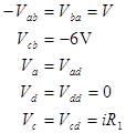
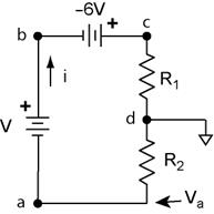
Kirchhoff’s voltage law (KVL). The sum of the voltages around any closed loop is zero. Use KVL to find V in the above example. KVL says that
![]()
In this case we don’t have enough information to completely solve the problem. If we also know that Vc = 4 V and Va = −3 V, what is V?
Discussion: In the above example, how much current flows to ground?
Current (symbol I) is the rate of flow of charge. It is measured in units of Amperes (usually called Amps) and abbreviated A. 1 Ampere = 1 Coulomb/second. Electrical current flows from positive to negative potential to (+ → −). Because electrons have a negative charge, electrons flow opposite to the flow of electrical current. The arrows define the direction of electrical current, the direction that hypothetical positive charges would flow, not the direction electrons flow! Two terms are used to describe the direction current flows into a terminal.
Source: current flows out of the terminal.
Sink: current flows into the terminal.
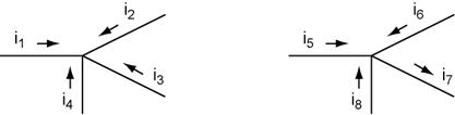
Kirchhoff’s current law (KCL). The sum of all currents flowing into a node is zero. Note that the direction of the current arrow defines the direction of positive value for the variable. Thus for a positive value of i5, current flows into the node, in the direction of its arrow. For a negative value of i5, current flows out of the node, opposite its arrow.
![]()
![]()
![]()
KCL Example![]()

Power
(symbol P) is the rate that energy is deposited in a circuit element; it
is measured in Watts, abbreviated W. ![]()
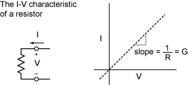
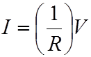
Resistance (symbol R) is the resistance to the flow of current. More specifically the resistance of a circuit element is the ratio of the voltage to the current. Resistance is measured in units of ohms, abbreviated Ω (the upper case Greek letter omega). The relationship between the current and the voltage is given by ohms law. 1 Ω = 1 V/A.
Ohm’s law is the fundamental relationship between current and voltage.
![]()
Conductance (symbol G) is the reciprocal of resistance. It is measured in units of siemans, abbreviated S. 1 S = 1 A/V. Older literature used the unit mho for conductivity (1 mho = 1 S); mho is ohm spelled backwards and the abbreviation is ℧, the upside-down omega!
The Resistor
The resistor is the most ubiquitous circuit element. Simply put, it resists the flow of current. In practical terms, the ratio of voltage across the resistor and the current through it is defined by its resistance. Ohm’s law states that a graph of current versus voltage for a resistor will be a straight line with a slope of 1/R.
Resistors in parallel: The equivalent resistance of resistors in parallel is the reciprocal of the sum of the reciprocals of the resistance of all of the parallel resistors.
All parallel circuit elements have the same voltage across them.
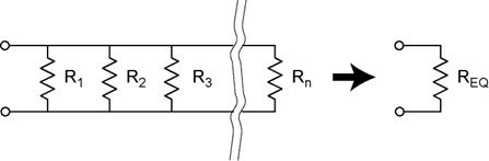
Resistances in parallel: ![]()
Conductances in parallel: ![]()
Resistors in series: The equivalent resistance of resistors in series is the sum of the resistance of all of the resistors.
All series circuit elements have the same current through them.
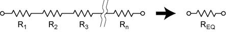
Resistances in series: ![]()
Conductances in series: ![]()
Potentiometer (AKA pot)
The potentiometer is a resistor with a third contact (arrow), which is internally connected to a wiper (sliding contact) that slides along the resistance material. The wiper position is controlled by a knob that adjusts the wiper position from one end of the resistor to the other. The wiper contact effectively divides the resistor into two resistors. For the purpose of analyzing a circuit containing a potentiometer, we include each of these resistors with the constraint that their series resistance is constant. We include the adjustability in the parameter x, which divides R into two resistors of values xR and (1−x)R.
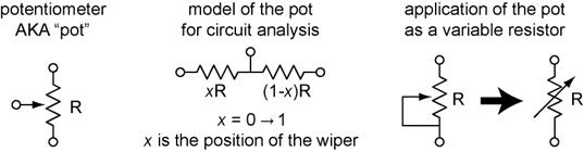
Variable resistor application: If a simple variable resistor (two terminals) is desired, the wiper is connected to one of the end terminals, shorting one of the ‘resistors’. Adjustability is commonly designated in schematic symbols by an arrow placed through the symbol at an angle.
Power
in Resistors: The fundamental definition of power, ![]() , can be
expanded because current and voltage are related by the resistance. Therefore
we can eliminate either current or voltage from the equation.
, can be
expanded because current and voltage are related by the resistance. Therefore
we can eliminate either current or voltage from the equation.
![]()
It is important to note that the power will be zero for any value of I if V = 0 and for any value of V if I = 0. These two cases correspond to R = 0, a short circuit, and the second to R → ∞, an open circuit.
Ideal conductor
Ideal conductors have zero resistance. The components of the circuit schematic are connected by ideal conductors. These are simply the lines used to connect the schematic symbols. Once we are used to the idea we take this for granted.
If we are constructing a circuit model of a real circuit and need to take the resistance of the real wires into account, we do this by adding a resistor.
Ideal Meters,
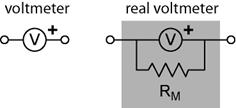
The ideal voltmeter measures voltage and has infinite resistance. No current flows through an ideal voltmeter. Voltages have a sign. The sign of the voltage you read will depend on which terminal is connected to the reference point. In the symbol below we define the + terminal so that the voltage reading is positive if the + terminal is more positive with respect to the “common” terminal.
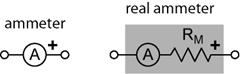
The ideal current meter (ammeter) measures current and has zero resistance. There is no voltage drop across an ideal ammeter. Currents have a sign. The sign of the current you read will depend whether the + terminal sources or sinks the current. In the symbol below we define the + terminal so that the current reading is positive if current flows into the + terminal. Thus if we connect the + terminal of the ammeter to a positive voltage (through a resistor please!) the current will read positive.
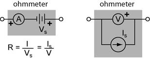
What about the ohmmeter? Yes we will use the ohmmeter in lab to measure resistance, but it is actually a combination of a voltage source and ammeter or a current source and voltmeter. Ohms law is then used to calculate the resistance. The ohmmeter is not a fundamental construct.
ideal sources
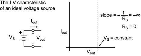
Voltage Source
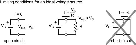
The ideal voltage source maintains a constant voltage across its terminals. It can source or sink any current to the circuit to make this true. It is a hypothetical construct. However the value of current cannot be infinite.
One circuit that does not make sense for an ideal voltage source is the short circuit. The voltage across a short circuit is zero. This second constraint means that the only valid value for the short circuited ideal voltage source is Vs = 0. The open circuit is OK.
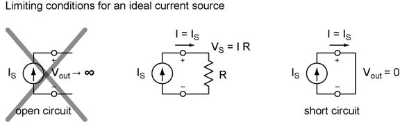
Current Source
The ideal current source maintains a constant current flowing through its terminals. It can generate any voltage necessary to make this true. It is a hypothetical construct. However the value of voltage cannot be infinite. Positive current is defined in the direction of the arrow. If Is is negative, this means that the current is flowing in the direction opposite to the arrow in the symbol.
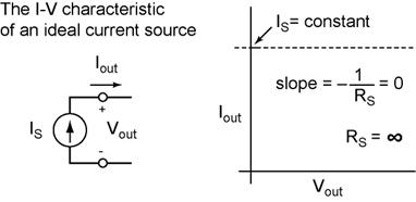
One circuit that does not make sense for the ideal current source is the open circuit. No current can flow in an open circuit. This second constraint means that the only valid value for the open circuited ideal current source is Is = 0. The short circuit is OK.
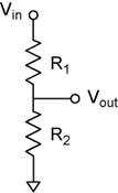
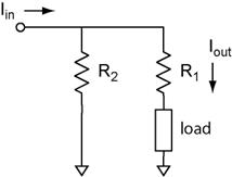
Applications
All circuit problems can be solved using KVL, KCL, and Ohm’s Law. This is true regardless of the complexity of the circuit. Very powerful techniques such as mesh analysis can be used to efficiently handle the mathematical problem. However this does not give us a feeling for what is really happening in the circuit. The trick to understanding an electronic circuit is to learn how to break it down into blocks and to understand what these blocks do. Two basic constructs that are found over and over again in circuits are the voltage divider and the current divider. Although they may at first seem trivial and of limited use, these constructs are the basis of filters and amplifiers. More on this later in the course, or simply look ahead in the book!