Notes on AC steady-state circuits, AC impedance, RC, RL, & RLC filters
Welcome to the frequency domain!
There is a fundamental principle of nature that any time dependent signal can be broken down into its component frequencies (its frequency spectrum). Because of this, it is very useful to describe the characteristics of a circuit in terms of pure frequencies. For this reason we can calculate the behavior of the circuit at all frequencies which will determine how the circuit changes each frequency component of the signal.
Vectors and complex numbers.
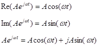
A = Aejωt We represent a sine wave of frequency f as a complex exponential
A is the complex amplitude.
A is the magnitude of the amplitude.
![]() In
electronics we use j rather than i to avoid confusion with the
current.
In
electronics we use j rather than i to avoid confusion with the
current.
ω = 2πf is called the angular frequency which has units of radians per second
t is time.
We will base our analysis on complex exponentials rather than sines and cosines because the mathematics is much simpler. (No trig identities are required!) Note that
Impedance
For AC circuits we introduce a new concept: impedance, which has the symbol Z and units of ohms. This is a generalized circuit element that can be a resistor, capacitor, inductor, or any complex network. Furthermore impedance is frequency dependent and is a vector quantity—it has both magnitude and phase. In circuit analysis Z behaves similarly to R. It combines in series and parallel just like R.
Impedances in parallel: The equivalent impedance of impedances in parallel is the reciprocal of the sum of the reciprocals of the impedances of all of the parallel impedances.
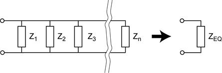
Impedances in parallel: ![]()
Impedances in series: The equivalent impedance of impedances in series is the sum of the impedances of all of the impedances.
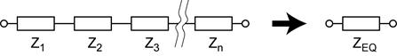
Impedances in series: ![]()
Resistors
Resistors conduct AC no differently than DC. Unlike capacitors and inductors, the impedance of a resistor is not dependent on frequency. The current and the voltage are in phase. The relationship between the current and the voltage is given by Ohm’s law.
![]()
Thus the current through a resistor is always in phase with the voltage across the resistor.
![]()
Capacitors
Capacitors conduct AC, the higher the frequency, the lower the impedance. At zero frequency (DC) capacitors have infinite impedance. The current and the voltage are out of phase by 90º. The relationship between the current and the voltage is given by Ohm’s law.
![]() .
.
The current through a capacitor leads the voltage across the capacitor by 90º.
![]()
Inductors
Inductors impede AC, the higher the frequency, the greater the impedance. At zero frequency (DC) inductors have zero impedance. The current and the voltage are out of phase by 90º. The relationship between the current and the voltage is given by Ohm’s law.
![]()
The current through an inductor lags the voltage across the inductor by 90º.
![]()
Decibels
The decibel is a logarithmic measure of relative power and relative amplitude. The decibel is defined as
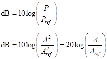
Note that the ratio of the amplitudes is actually the ratio of the amplitudes squared. The square can be pulled out of the log and changes the 10 to 20. The most common quantities that we measure in the lab are amplitudes—voltage, current, and impedance.
The decibel is used in two different ways.
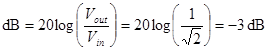
As a relative measure where Pref and Aref are not absolute quantities. Example. A voltage divider with Vout/Vin=1/√2. In this case, we are interested in the ratio not the actual value of Vout. This voltage divider attenuates the voltage by 3 dB.
As an absolute measure where Pref and Aref are absolute quantities. These reference levels must be defined. Typical reference levels and the dB abbreviations are shown in the following table.
|
abbreviation |
reference level |
|
dBm |
1 mW |
|
dBV |
1 V |
|
dBmV |
1 mV |
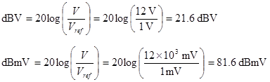
Example. What is 12 V in dBV and in dBmV? The reference levels will be 1 V and 1 mV respectively.
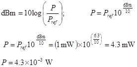
Example. The cable guy has just installed cable at your house. He says that you have a nice strong signal. He measured its power at 6.3 dBm. How much power is that in Watts?
Significant Figures and Logarithms.
A logarithm is composed of two parts. The characteristic is the number to the left of the decimal point. It determines the order of magnitude of the number (locates the decimal point). The mantissa is the number to the right of the decimal point and carries the numerical value. The number significant figures in the number determine the number of significant of digits in the mantissa (the number of significant decimal places).
Example: log(3.4×10¹⁴)
= 14.53
3.4×10¹⁴ has two significant figures, therefore
its logarithm will have two significant figures after the decimal point.
Note that its logarithm has a total of four significant figures. We can
use the property of logarithms to show how this arises. After rounding the
correct result is obtained.
log(3.4×10¹⁴) = log(3.4) + log(1014) = (0.531) + (14) = +14.531 → 14.53
Example: 10−34.2
= 6×10⁻³⁵
−34.2 has three significant figures, but only one
is right of the decimal point, so its anti-log only has one significant figure.
log(6×10⁻³⁵) = log(6) + log(10−35) = (0.778) + (−35) = −34.222 → −34.2
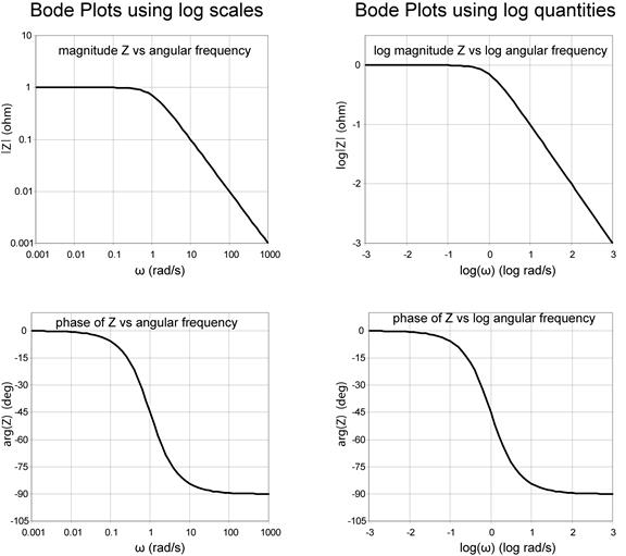
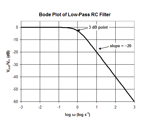
The Bode Plot
“Spectra” in electronics are commonly represented as a Bode Plot, named after Hendrik W. Bode. (It is pronounced Bo-dee.). Typically we will get two plots, log magnitude vs log frequency and phase vs log frequency. Note that because decibel is already a logarithmic quantity, dB can be plotted directly on the y axis. The following Bode plot is for the equivalent impedance of a parallel RC network. (R = 1 Ω, C = 1 F)
Summary: Resistors, Capacitors, and Inductors
|
Summary |
|||
|
|
resistors |
capacitors |
inductors |
|
series |
|
|
|
|
parallel |
|
|
|
|
stored energy |
0 |
|
|
|
power dissipated in |
|
|
|
|
DC steady state |
|
|
|
|
transient |
|
|
|
|
time constant |
|
|
|
|
continuous variable |
|
V |
i |
|
impedance |
|
|
|
|
reactance |
|
|
|
|
AC steady state |
The current through the resistor is always in phase with the voltage across the resistor. |
The current through the capacitor is always 90º out-of phase with the voltage across the capacitor. The current LEADS the voltage by 90º. |
The current through the inductor is always 90º out-of phase with the voltage across the inductor. The current LAGS the voltage by 90º. |


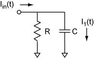 The Current Divider revisited. The circuit to the right
can be thought of as a current divider which is dependent on frequency. We are
asked to find the complex amplitude of I1/Iin
as a function of angular frequency ω. In addition we are asked to find
the quantities derived from the complex amplitude: real amplitude, imaginary
amplitude, magnitude, and phase, as a functions of angular frequency.
The Current Divider revisited. The circuit to the right
can be thought of as a current divider which is dependent on frequency. We are
asked to find the complex amplitude of I1/Iin
as a function of angular frequency ω. In addition we are asked to find
the quantities derived from the complex amplitude: real amplitude, imaginary
amplitude, magnitude, and phase, as a functions of angular frequency.
The step-by-step solution:
 First find
the complex amplitude of I1/Iin.
First find
the complex amplitude of I1/Iin.
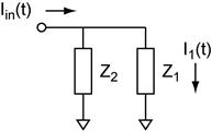
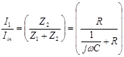
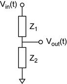
Step 1: Think of the circuit as impedances (see circuit to the right). Solve for the quantities desired in terms of the impedances Z. Simplify the algebra at this point. It will help you later.
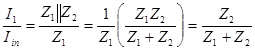
Step 2: Substitute
the particular impedances for each of the components
Resistors: Z→R; Capacitors Z→1/jωC; Inductors Z→jωL
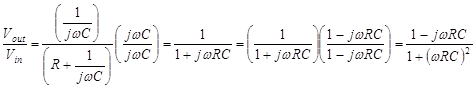
Step 3: Simplify the expression. The final answer should not have j in the denominator. The final answer should not be a complex fraction (no fractions in the numerator or in the denominator). My strategy is to take this a step at a time so that I can easily check my results.
Step 3A: Eliminate the complex fraction:
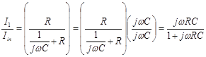
Step 3B: Eliminate j from the denominator:
![]()
This result is the complex amplitude. It contains the complete behavior of the quantity as a function of frequency. The complex amplitude is a vector quantity.
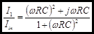 Even though an ωRC term can be factored out of the numerator,
doing so sacrifices the advantage of clearly separating the numerator in real
and imaginary parts.
Even though an ωRC term can be factored out of the numerator,
doing so sacrifices the advantage of clearly separating the numerator in real
and imaginary parts.
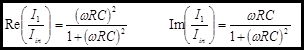
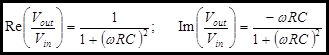
Step 4: Solve for the quantities derived from the complex amplitude.
The real and imaginary parts of the complex amplitude can be easily obtained. The physical significance of the real and the imaginary parts. The real part is the in phase component of the magnitude. The phase in this case is measured with respect to Iin. In vector terms this would be the dot product of the I1 with Iin. The imaginary part is the out-of phase component of the magnitude. In vector terms this would be the component of the I1 perpendicular to Iin.
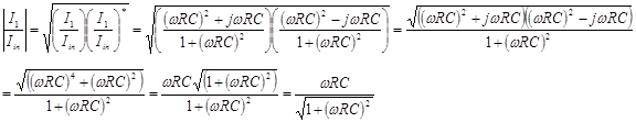
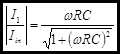
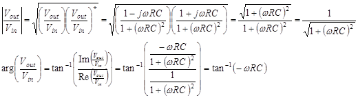
The magnitude
of the complex amplitude is the most useful of the quantities you will derive
from this analysis. It is simply the magnitude of the vector. It is easily
calculated for the complex amplitude by using the definition![]() .
.
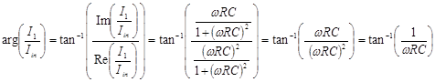
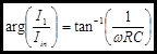
The forth quantity is the phase. This is just the angle of the complex amplitude vector with respect to the positive real axis. It is easily obtained from the real and imaginary parts of the complex amplitude.
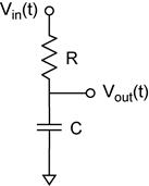 The Voltage Divider revisited. The circuit to the right
can be thought of as a voltage divider which is dependent on frequency. We are
asked to find the complex amplitude of Vout/Vin
as a function of angular frequency ω. In addition we are asked to find
the quantities derived from the complex amplitude: real amplitude, imaginary
amplitude, magnitude, and phase, as functions of angular frequency.
The Voltage Divider revisited. The circuit to the right
can be thought of as a voltage divider which is dependent on frequency. We are
asked to find the complex amplitude of Vout/Vin
as a function of angular frequency ω. In addition we are asked to find
the quantities derived from the complex amplitude: real amplitude, imaginary
amplitude, magnitude, and phase, as functions of angular frequency.
The step-by-step solution:
 First find
the complex amplitude of Vout/Vin.
First find
the complex amplitude of Vout/Vin.
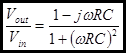
Step 1:
![]()
Step 2:
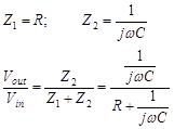
Step 3:
The complex amplitude is:
Step 4:
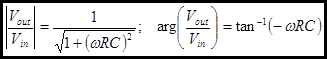
Lets look at
our results. We are particularly interested in the magnitude. The
denominator is ![]() . At low
frequencies where 1>>
. At low
frequencies where 1>>![]() the
magnitude is nearly unity. At high frequency where 1<<
the
magnitude is nearly unity. At high frequency where 1<<![]() the
the ![]() term dominates so that
term dominates so that
![]() ,
,
thus the
magnitude drops off like 1/ω in this region. The transition between the
two regions occurs at the point where 1=![]() hence
hence
![]() .
.
We can solve for the frequency of this point and obtain the following important result.
![]()
I have labeled this frequency with the subscript C because it is often called the corner frequency. Sometimes you will see the equation of the magnitude written in this form:
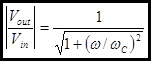
In these calculations remember that farad × ohm = second. You will also need to use the context of the equation to distinguish between ω and f, because formally they both have units of second−1, so be careful!
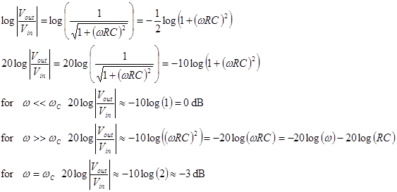
Our results can
be summarized as a Bode plot. By plotting ![]() in
dB versus log(ω) we see that
in
dB versus log(ω) we see that ![]()
Resonant Circuits RLC
We can combine the three elements R, L, and C in series and parallel. In this section we will work out the equivalent impedance of each combination.
Parallel RLC
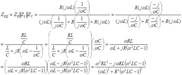
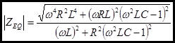
We will set out to find the equivalent impedance of the parallel RLC Network.
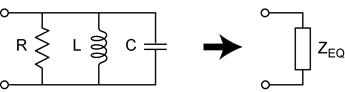
First set up and simplify the complex impedance of the network.
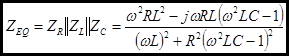
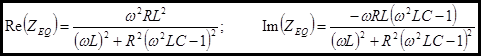
Now we can easily find the real and imaginary parts.
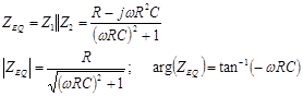
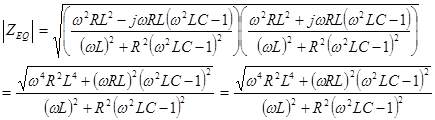
The magnitude of the impedance:
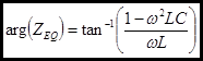
And the phase:
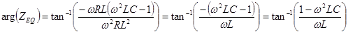
Note the term ![]() that appears in these
equations. This term goes to zero at the resonance where
that appears in these
equations. This term goes to zero at the resonance where
 .
.
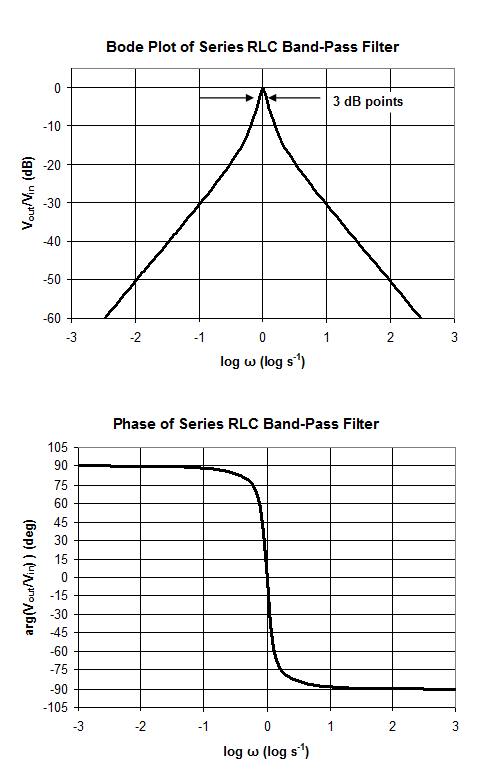
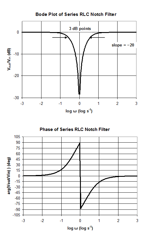
RLC Band Pass and Notch Filters
The filters shown have their pass band and notch centered at ω = 1 rad/sec, because we have chosen R = 1 Ω, C = 1 F, and L = 1 H. The center of frequency is determined by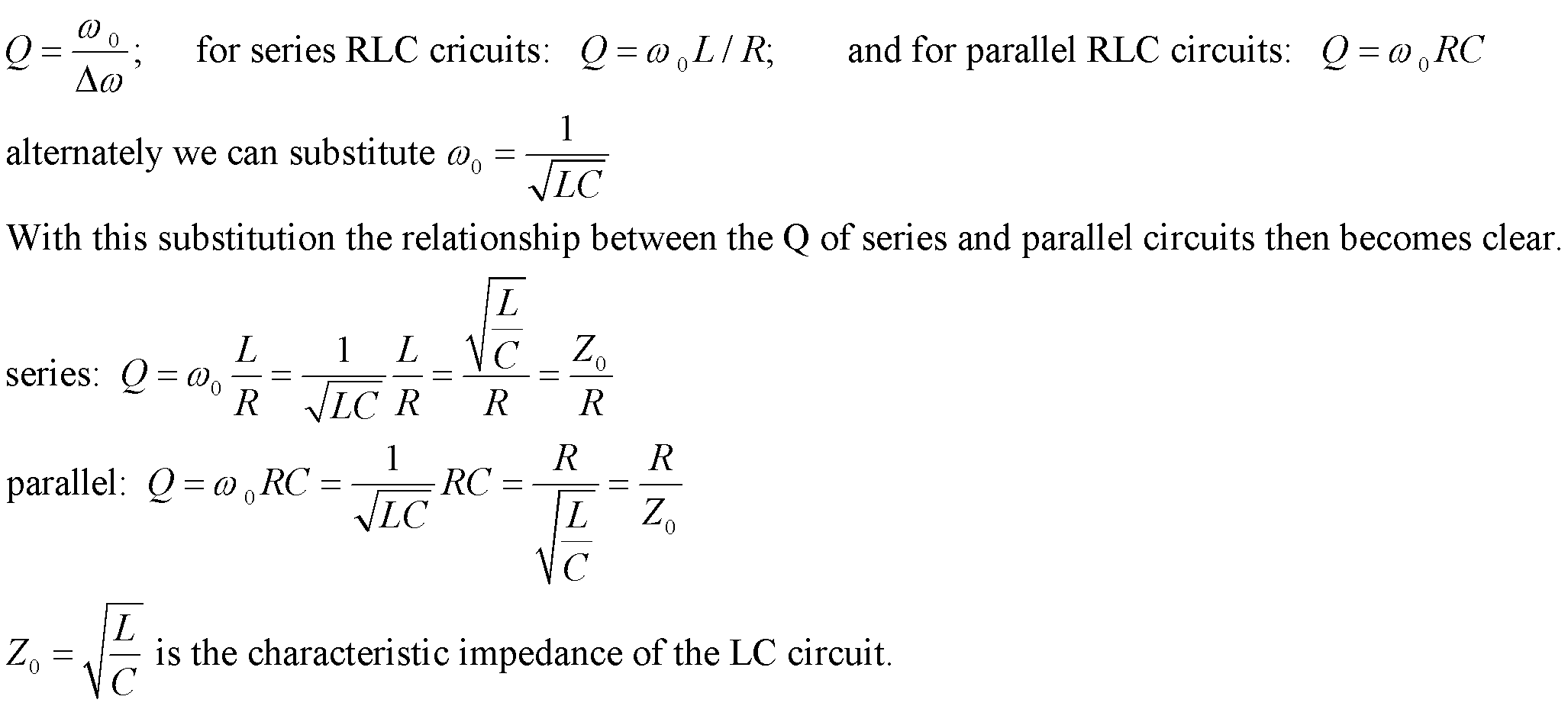
Units: In these calculations remember that farad × henry = second2. You will also need use the context of the equation to distinguish between ω and f, because formally they both have units of second−1, so be careful!
Note also that Henry / Farad = Ohm2.
Band Pass Filters
Q is also related to the dissipation (damping) in the
resonant circuit.
![]()
Notch Filters (Band Reject Filters)
Vocabulary
You should be able to define the following terms. If it is not explicitly defined in this handout, check the assigned reading in your text.
angular frequency
argument
band-pass filter
band-reject filter
Bode plot
characteristic
complex amplitude
complex conjugate
corner frequency
decibel
high-pass filter
imaginary part
impedance
low-pass filter
magnitude
mantissa
notch filter
phase
quality factor (Q)
real part
3dB point
