Lab 12: Op Amps: Characteristics and Applications
In this lab you will build 6 different op amp circuits.
In order to do this lab you need to understand the characteristics of operational amplifiers (op amps).
Reading Ch 8.0-4 + lecture notes.
Components:
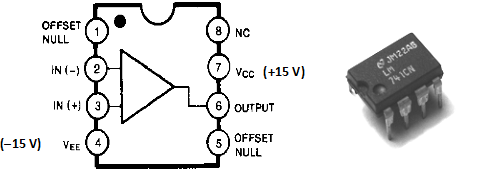
The following circuits use the 741 op amp in the 8-pin DIP package.
Op Amp Golden Rules (memorize these rules)
1) The op amp has infinite open-loop gain.
2) The input impedance of the +/− inputs is infinite. (The inputs are ideal voltmeters). The output impedance is zero. (The output is an ideal voltage source.)
3) No current flows into the +/− inputs of the op amp. This is really a restatement of golden rule 2.
4) In a circuit with negative feedback, the output of the op amp will try to adjust its output so that the voltage difference between the + and − inputs is zero (V+ = V−).
Throughout this lab you will measure the input and output waveforms using the oscilloscope with your scope probes.
PART 1) The Voltage Follower. We have already made voltage followers in the BJT and FET labs. Op amps can also be used as a voltage follower. It is a very simple circuit, which requires no resistors, only the op amp and power!
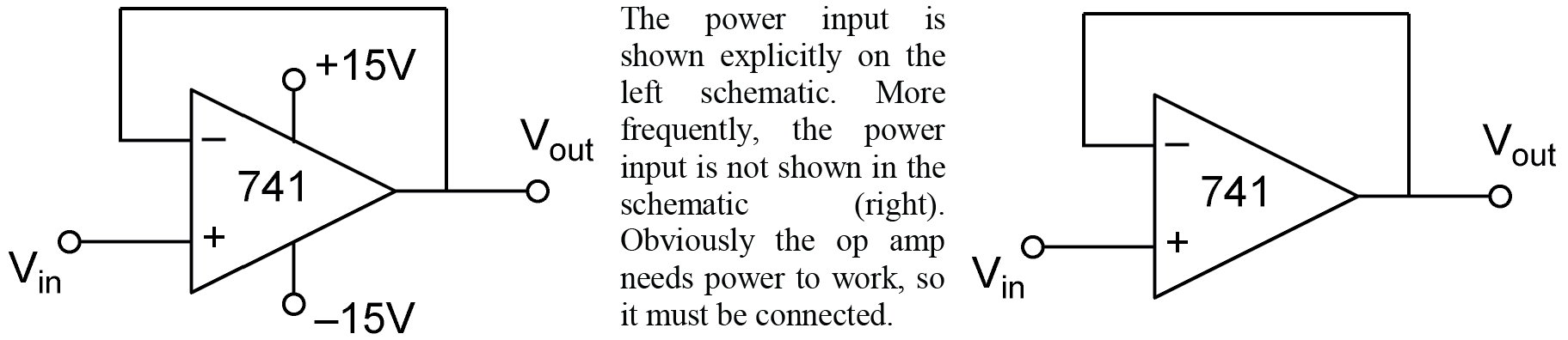
Construct the circuit above. Drive it with a 100 mVp-p amplitude 1 kHz sine from your function generator. Use two scope probes to measure both the input and output waveforms simultaneously.
Q 1) 2pts. Measure Vout, Vin, and calculate Vout/Vin. It should be very close to unity. Is there a noticeable phase shift?
Q 2)
2pts. Vary the input frequency. As you increase the frequency Vout
will begin to deviate from Vin both in magnitude and in phase.
At what frequency does ÷Voutç=÷Vinç/Ö2
?
Q 3) 2pts. As you decrease the frequency, does Vout continue to track Vin? Adjust the DC offset of the function generator. Does Vout also track the DC offset?
Now with 50 kHz sine wave input, increase the amplitude. Does the output waveform change? You are seeing an effect called slew rate limiting, because there is a maximum rate that the output voltage can change. This is a large signal behavior of real op amps. We will largely ignore it in this lab, but it is important to be aware of it so you can recognize the effect. Later in the lab, if you see this effect, you will need to reduce the input amplitude.
Q 4) 4pts. As you vary the amplitude if Vin, you will see that the slope of the Vout waveform is roughly constant. Measure the slope of the linear part of the waveform. Calculate the slew rate and report it in V/μsec.
PART 2) Inverting Amplifier. The op amp is a very useful device. Op amp circuits are very predictable—that is they work the way you expect without tinkering. The inverting amplifier is one of the most common op amp circuits. Construct the inverting amplifier shown below. You will use four different values for R1 (see table). Measure the resistances of each of your R1 resistors and R2 with the DMM. Record them in the table in your lab notebook. (Note: you will use the same resistors in the next part too.) Drive the input with a 1 kHz sine wave. Measure Vin and Vout using your scope probe. Make sure the output does not clip, otherwise you will get an erroneous Vp-p! One strategy is to adjust the input amplitude so that the output amplitude is ~10 Vp-p. But you can do it any way that is convenient for you. You should observe that Vout is 180° out of phase with respect to Vin, this is just the same as multiplying by –1, so we say the gain is negative or inverting.
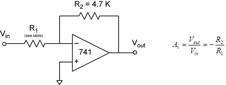
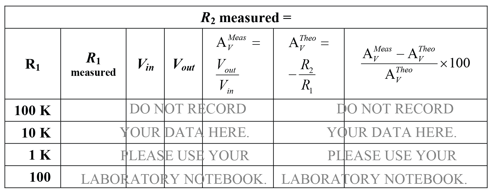
Table 1) 10pts. Complete the calculated columns in your notebook. Compare the measured gains to the theoretical gains based on the measured resistor values. What is the average percent deviation from the theoretical gain?
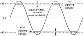
Q 5) 4pts. Now with your op amp configured for the highest gain, set the input for a 1 kHz sine wave input. Increase the amplitude. Does Vout get clipped? (See the diagram below.) What are the minimum and maximum clipping voltages? What is the difference between the clipping voltages and the supply voltages?
Sketch 1) 5pts. Using the same set up as in Q5, clip a second scope probe to the node of the inverting op amp input V–. According to the op amp golden rules, what should the V– be in this circuit? Adjust Vin for the lowest input amplitude. What do you see? Sketch the V– and Vout waveforms labeling their approximate amplitudes. These are effects of real op amps. If the op amp had infinite loop gain, V– = V+ would be correct. For finite loop gain, some finite difference between V– and V+ is required to drive the op amp output to change.
Sketch 2)
5pts. Increase Vin until Vout is clipping. Sketch the
waveform again showing approximate amplitudes. What can you say about V–
and the op amp golden rules when the output is clipping?
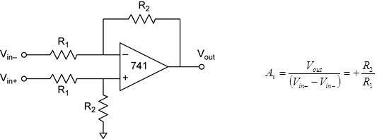
PART 3) Non-inverting Amplifier. Construct the non-inverting amplifier
shown below. The non-inverting amplifier has the advantage that the input
impedance is very high. You will use four different values for R1
(see table). Measure the resistances of each of your R1 resistors
and R2 with the DMM. Record them in the table in your lab notebook. Drive
the input with a 1 kHz sine wave. Measure Vin and Vout
using your scope probe. Make sure the output does not clip, otherwise you will
get an erroneous Vp-p! One strategy is to adjust the input amplitude
to that the output amplitude is ~10 Vp-p. But you can do it any way
that is convenient for you. You should observe that Vout is in phase
with respect to Vin, so we say the gain is positive or non-inverting.
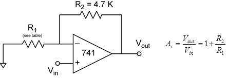
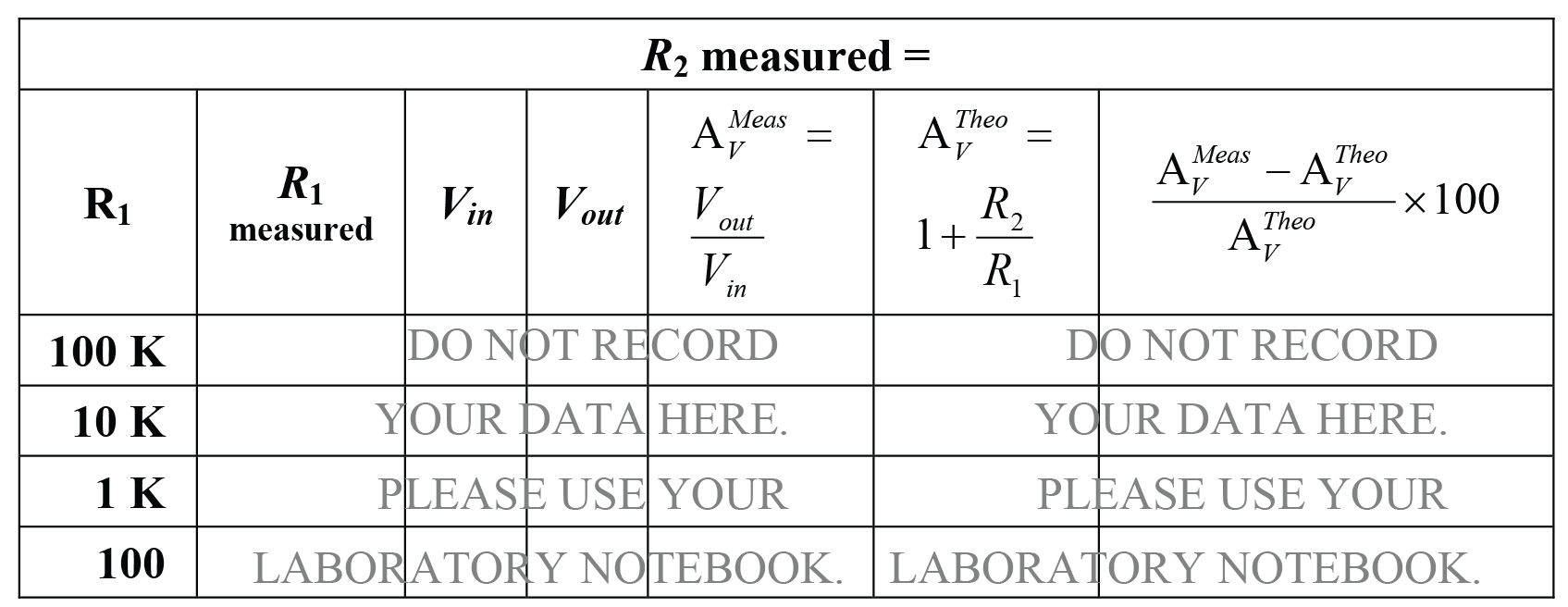
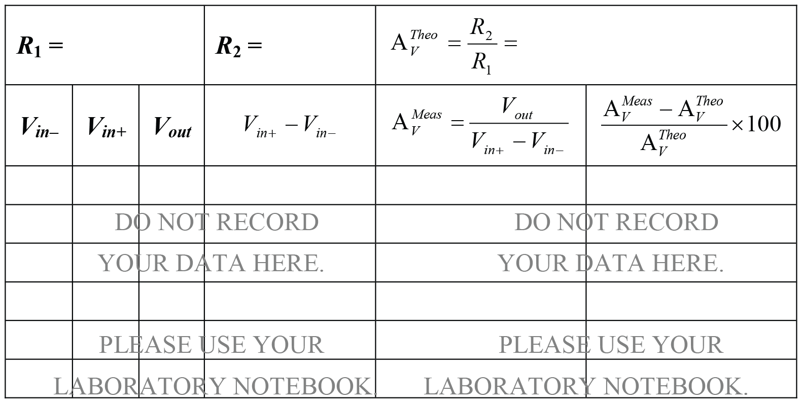
Table 2) 10pts. Complete the calculated columns in your notebook. Compare the measured gains to the theoretical gains based on the measured resistor values. What is the average percent deviation from the theoretical gain?
PART 4) Differential Amplifier. You have seen many examples in the class where we wanted to measure the voltage between two points in the circuit, but instruments like the oscilloscope can only measure the voltage to ground. The differential amplifier can be used in this case. Its output is the difference between the two input voltages. Furthermore the output is referenced to ground, so it is easily measured with oscilloscopes, etc. There are many other applications of differential amplifiers.
Build the following differential amplifier. Select the resistors for a gain of ~4. Choose R1 no smaller than 1K so that the input impedance is at least 1K. You will need two of each resistor. Record the nominal resistances of R1, and R2, in the table in your lab notebook, you do not need to measure them. Construct two simple voltage divider voltage sources from 100K potentiometers connected to the +15V and –15V power supplies. (You will use these voltage sources in the next part too.) Measure Vin–, Vin+, and Vout for 6 different combinations of Vin– and Vin+. At least half of your input voltages should be >+5V or <–5V to illustrate that this is truly a differential measurement. You can use your DMM for the measurements in part 4.
Q 6) 2pts. You should observe that changing Vin+ will change Vin–, but the reverse is not true. Why is this? Explain using the characteristics for the op amp and your voltage sources.
Table 3) 15pts. Complete the calculated columns in your notebook. Compare the measured gains to the theoretical gains based on the nominal resistor values. What is the average percent deviation from the theoretical gain?
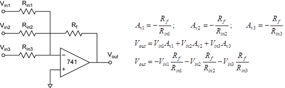
PART 5) Summing Amplifier. The inverting amplifier has special properties. Multiple inputs can be added, which then sum together in the output. Each input has a gain defined by Rin and Rf as it is with the simple inverting amplifier. Note this summing function is only possible because the V– node is held at virtual ground, by the op amp.
Build the following summing amplifier. Select three different input resistors. The minimum gain should be unity. The maximum gain should be 10. No Rin should be less than 1K so that the input impedance is at least 1K. Construct three simple voltage divider voltage sources from 100K potentiometers connected to the +15V and –15V power supplies. Measure Vin–, Vin+, and Vout for 6 different combinations of Vin1, Vin2, and Vin3.
Connect all three input voltages and make sure the Vout is not clipping. You can do this by testing that Vout is within the clipping limits you have already observed and that it is responsive to the change of each input voltage. Make six measurements so that you have three pairs of measurements where only one Vin is changed. Vout should change by at least 1V. For example, measure Vout with two different Vin1 and the same Vin2 and Vin3. Although it is possible to do this experiment with a minimum of four measurements, that requires you to accurately return the changed input to its initial value—a task that can take longer than simply making a new set of measurements! You can use your DMM for the measurements in part 5.
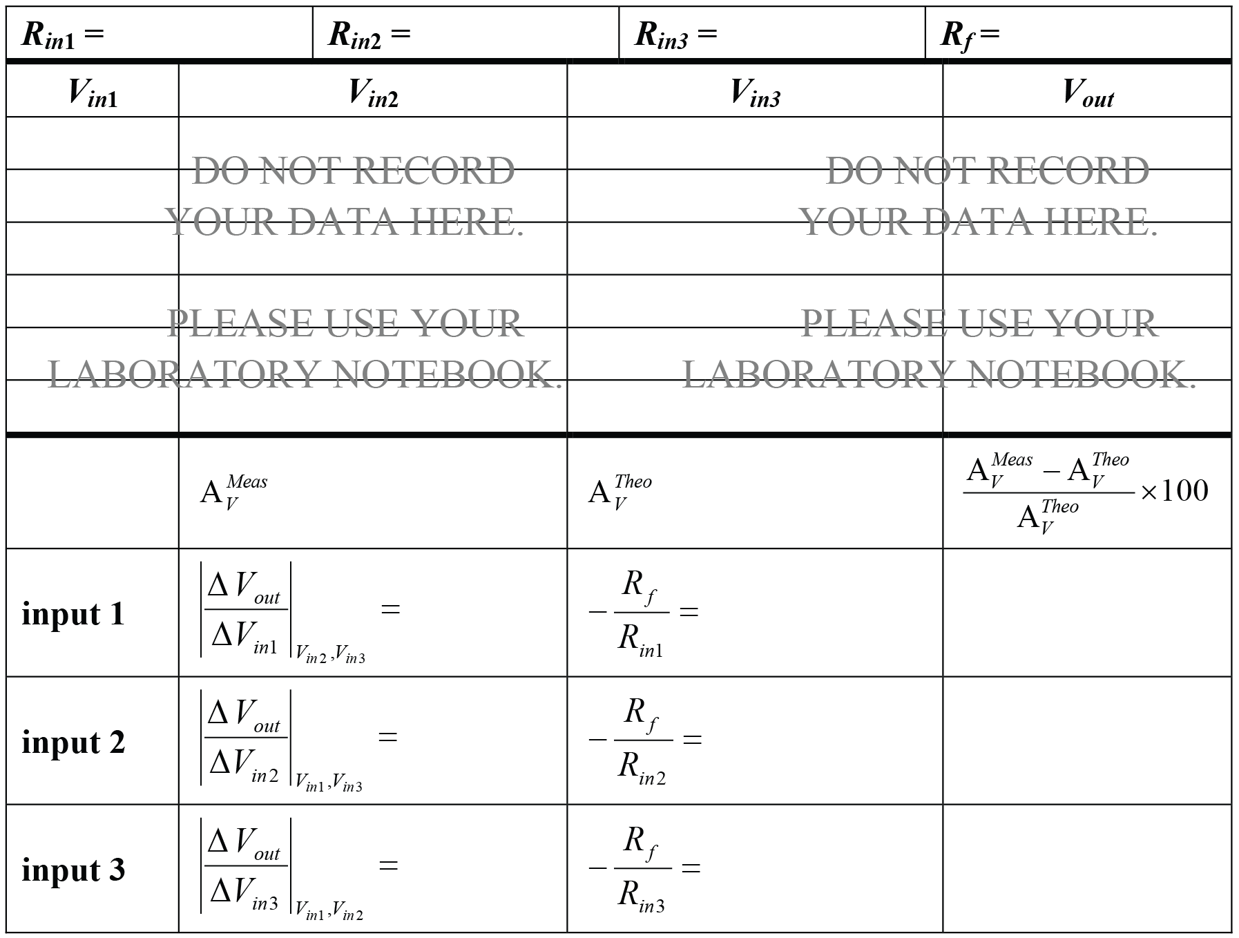
Table 4) 15pts. Complete the calculated columns in your notebook. You will compare the measured gain for each input to the theoretical gain based on the measured resistor values. Because you have designed the experiment so that you make two different sets of measurements while holding the other two constant; the gain for each input is easily calculated. The fancy mathematical notation of that statement is below.

Q 7) 2pts. In this experiment we used DC voltages to measure the gain. Propose another simple method to separately measure the gain of each input using equipment you have used in Elab.
PART 6) Transimpedance Amplifier. In this experiment we will use the oscilloscope to graph and to measure the I-V characteristic of a few components—the device under test (DUT)—e.g. resistors, diodes, capacitors, etc. The DUT is anything you want to stick in!
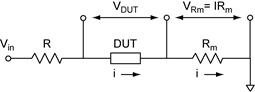
A common way to measure current is to insert a “measuring” resistor, Rm, into the circuit and then measure the voltage drop across it. The resistor in this case functions as a current-to-voltage converter. Its advantage is its simplicity. Its disadvantage is that one of the voltages we need to measure in order to construct the I-V graph is not referenced to ground (see circuit below).
In this experiment we place the measuring resistor in the feedback loop of an op amp to hold the DUT-Rm junction at ground. This construct is called a transimpedance amplifier or current-to-voltage converter. The only current path is the series-connected DUT and Rm. A current flowing through the DUT, as shown, creates a voltage drop across Rm. The op amp feedback makes its output swing negative forcing the DUT-Rm junction to ground. So VDUT is now referenced to ground! VRm is also referenced to ground, but inverted. Measurements of VRm is easily converted to current. This amplifier has transimpedance gain, which has units of volts per amp. The resistor, R, is present to limit the current. Because its voltage drop is outside the measurement area, it will not disturb your results.
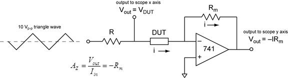
Build the circuit above. Use 1K for both resistors, and a 10K resistor for your initial DUT. Initially drive your circuit with a 10 Vp-p 100–1000 Hz triangle wave with zero DC offset. You can then adjust it as needed.
Oscilloscope set up. So far in this lab the x axis of the scope has been provided by scope’s time base. We can also use it to graph one voltage (y axis) against another (x axis). To do this, on the horizontal menu, select: time base = X-Y. Channel 1 becomes the x input and channel 2 the y input. Initially set x=0V and y=0V to the center of the screen. Set the channel 1 input to ground, then center the spot in x using the vertical offset on channel 1. Next, set the channel 2 input to ground, then center the spot in y, using the channel 2 vertical offset adjustment. In this experiment, we use the triangle waveform driving the circuit to provide a linear sweep in voltage on the x axis. With the 10K resistor as the DUT, set channel 2 to invert (CH2 menu: invert = on) so that the current is positive for positive voltage. This will set the I-V graph display in the conventional way. A resistor should have a positive slope and exist only in quadrants I and III.
Sketch 3) 5pts. Make a sketch of the I-V graph of the 10K resistor from the scope. Measure the current at 2 V using the scope. (Hint: convert the measured voltage from the current-to-voltage converter back to its input current.) Calculate the resistance of the 10K resistor. Compare this to the resistance you measure with the DMM.
Sketch 4) 5pts. Make a sketch of the I-V graph of the 1N4148 diode from the scope. Measure the forward voltage drop at 1 mA from the oscilloscope. Compare this to the Vf = 0.6V we have been using as a rule of thumb.
Sketch 5-6) 10pts (5pts ea). Make a sketch of the I-V graph of two different color LEDs. Measure the forward voltage drop at 1mA from the oscilloscope. Reduce the frequency of the triangle wave to less than 1 Hz so you can see when the LED turns on. Indicate on your sketch, when the LED is illuminated. Which LED has the larger voltage drop, the one with the larger or smaller photon energy?
Q 8) 2pts. In this experiment we used the op amp current amplifier to make both VDUT and VR referenced to ground. This is not the only op amp solution. Propose another op amp circuit that would have the same function, with VDUT and VR outputs referenced to ground. Draw the schematic, showing the op amp, resistor(s), DUT, etc.
