
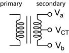
Measure the Output of Your Transformer. Use the oscilloscope with the 10X probe to measure the peak voltages from your transformer. Measure and sketch: Va to Vb, Va to VCT, and Vb to VCT .
Q1) 5pts. Sketch the three (3) waveforms and measure peaks. Be sure to label the peak voltages on your sketch.
Q2) 5pts. What is the maximum power you can get from your function generator? Consider that its Thevenin equivalent circuit is a 10 Vp-p AC sine wave source with a source resistance of 50 Ω. This is a question for later. (Hint: Please refer to the section of the Thevenin-Norton lecture notes handout Maximum Power Transfer.)
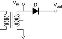
The Half-Wave Rectifier. The simplest DC supplies can be made using one rectifier. The disadvantage is that it only provides power for half of the cycle. Build the following circuit and sketch the output wave form.
Q3) 2pts. Sketch the waveform and measure peak voltage of the output and compare it to the peak voltage of the transformer.
Most circuits that require a steady source of DC power rather then the train of DC pulses produced by the previous circuit. Clearly the half wave rectifier cannot produce any power during the half cycle when the diode is reverse biased. What we need it a way to store energy during the half cycle when the diode is conducting and release it during the half cycle when it is not. This is achieved with a capacitor. The capacitor charges up to the peak voltage and then can discharge into the load during the next half cycle.
CAUTION: The capacitors you are using are polarized. Be sure that they are connected to your circuit in the correct with the correct polarity. The polarity is marked on the capacitor.
10μF
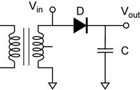
Q4) 2pts. Sketch the waveform and measure peak voltage of the output and compare it to the peak voltage of the transformer.
Q5) 2pts. In this circuit, how many diode drops Vf are between the transformer and the output?
The Two diode Full-Wave Rectifier. Two half-wave rectifiers can be connected so that the diodes conduct during alternating half cycles. This configuration requires a center tapped transformer. An advantage of this circuit is that only two rectifiers are required. The disadvantage is that a large secondary winding is required.
Q6) 2pts. Sketch the waveform and measure peak voltage from Vout and compare it to Va and to Vb of the transformer.
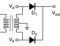
Add the capacitors shown in the schematic and repeat the above measurements.
Q7) 2pts. Sketch the waveform and measure peak voltage from Vout and compare it to Va and to Vb of the transformer.
10μF
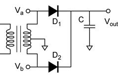
Q8) 2pts. In this circuit, how many diode drops Vf are between the transformer and the output?
The Full-Wave Bridge Rectifier. The bridge rectifier is a full-wave rectifier constructed from 4 diodes. Check and double check the direction of your diodes. If one is reversed it can destroy the other diodes.
Q9) 2pts. Sketch the waveform and measure the peak voltage from Vout and compare it to Vin.

Add the capacitors shown in the schematic and repeat the above measurements.
Q10) 2pts. Sketch the waveform and measure the peak voltage from Vout and compare it to Vin.
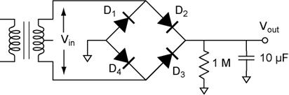
Q11) 2pts. In this circuit, how many diode drops Vf are between the transformer and the output?
The Voltage Quadrupler. In this section you will build a charge-pump voltage quadrupler. Read ch 4.2.5 (p417) for an explanation of how it works.
all
capacitors
1 μF
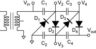
Q12) 5pts. Sketch the waveforms and measure the peak voltages for all the points shown in the diagram. Compare the voltages to Vin.
Q13) 5pts. For each point you measured above, how many diode drops Vf are between that point and Vin?
Q14) 5pts. What is the Thevenin equivalent circuit? Use the scope for these measurements. Set the automatic measurement to Vrms, this will accurately include the contribution of 60 Hz ripple on the DC output of the quadrupler, which is very pronounced under load. You have measured the open circuit voltage VTH. You need to calculate the source resistance. It is usually a bad idea to short circuit a power supply because it could be damaged. In this case use a 10 K resistor as the load resistor and then measure the output voltage while it is connected to the load resistor. Calculate the equivalent source resistance from these two measurements. (Show your calculations.)
Using your Voltage Quadrupler to Power a Neon Lamp Relaxation Oscillator. Connect the output of the voltage quadrupler to a 10 μF capacitor with a 1M resistor. Place the neon lamp in parallel with the capacitor. The neon lamp will flash. Monitor the voltage across the capacitor using the scope. Set the time base to 1 s/div. You should see a saw-tooth waveform. To make a voltage measurement, you can freeze the display using the Run/Stop button, then use the cursors to make measurements from the waveform.
10μF
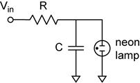
Q15) 2pts. What is the minimum and the maximum?
Q16) 1pts. What is the period (in seconds) of the flashing neon lamp?
Q17) 2pts. Based on the Thevenin equivalent circuit you found for the power supply, what is the RC time constant of this circuit? (Check your notes on RC transients. Hint: include both Rs and R.)
Q18) 2pts. What happens when you replace the 1 M resistor with a 330 K resistor? If the neon lamp does not flash (remains illuminated), try a 3.3 M resistor instead. What is the new period (in seconds) and the resistor you ultimately used?
