Lab 8: Diodes: Clippers, Clamps, Shifters, and Rectifiers
In this lab you will use the function generator and the oscilloscope to measure the voltages waveforms of various diode circuits.
In order to do this lab you need to understand the characteristics of diodes and zener diodes
Reading Ch 4.1-2, 5.3 + lecture notes.
Function generator set up. Connect the function generator to your circuit. Use a BNC Tee to also connect the function generator to channel 2 of your scope. Set the function generator to output a 100 Hz sine wave with a 5 Vp-p amplitude and zero DC offset. Trigger of the scope from channel 2 as you have done before.
Note that you will need to vary the amplitude up to 20 Vp-p to observe the full behavior of the circuits with the zener diodes.
Oscilloscope probes. Obtain a 1X scope probe and connect it to channel 1. Verify that CH1 is configured for the 1X probe.
Scope set up. Set up the scope so you can see the traces of both channels. Connect the probe to Vin. Verify that this voltage is and should be the same as observed in channel 2. Be sure to DC couple both oscilloscope channels!
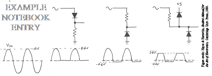
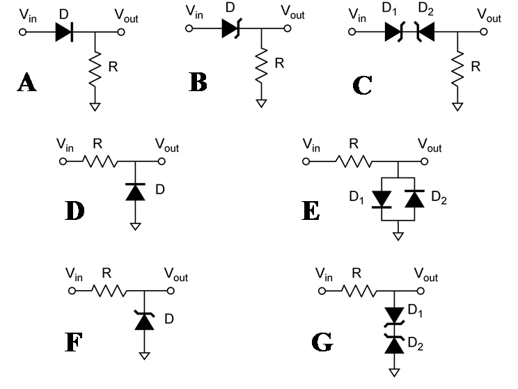
Construct the following circuits on the bread board. Compare the input waveform to the output waveform. Make a sketch in your lab notebook. These circuits behave differently in different regions of Vin. Your sketch should show these features and identify the effects of Vf and Vr where appropriate. The following is an example. Note the 9.4 V is Vin – Vf and that –0.6 V is –Vf.
Your lab report will consist of
1) sketches of the circuits and the
corresponding sketches of Vin and Vout
(similar to that shown above), (4pts ea)
2) Identify the function of the circuit according to the descriptions in the lecture
handout, (1pt ea)
3) answer the questions pertaining to circuits H and I, and (1.5pt
ea)
4) your notebook pages.
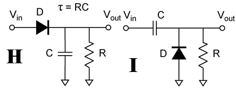
Components: In the following circuits, normal diodes are 1N4148, zener diodes are 1N4733, R = 10K, C = 1 μF.
Q1) 1.5pt. For circuit H, what is the significance of the time constant τ?
Q2) 1.5pt. If you want to use H as a peak detector, what factors will guide to in selecting τ?
For circuits H and I, R = 1 M.