Lab
3: Null Point Measurements:
open circuit voltage, source resistance, and meter resistance.
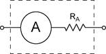
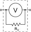
In this lab you will perform DC measurements and become familiar with basic test instruments — the digital multimeter (DMM) and the oscilloscope (scope). The ideal voltmeter draws no current (has infinite resistance) and the ideal ammeter has no voltage drop (zero resistance). Of course real meters do have an internal resistance. We can model real meters as a combination of an ideal meter and a resistor. In this lab you will see how these internal resistances can effect your measurements and how to measure the internal resistances.
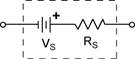
You are given a black box voltage source (VS). Your object is to measure the open circuit voltage and the internal resistance of the voltage source. You are not permitted to open the box. This is considered cheating.
Part 1) Quick Survey. The black box has 4 terminals. Only two of them have any internal connection. Use one of your DMMs in voltmeter mode to discover which terminals are connected and the polarity of those terminals. Record these findings for each terminal in your notebook along with the number on your box. The convention is to label terminals with no connection NC. Please do not make any marks on your black box.
Measure and record the voltage of your VS using your digital multimeters (DMM), and your oscilloscope (scope). Answer these questions for each of your measurements: What are the sources of error in each of these measurements? Estimate the accuracy of each of these readings. Do these measurements agree? If not hypothesize why they are different.
Part 2) Null point measurement. In this part we will measure the voltage of your VS by comparing it to a standard voltage using a voltage divider. A null-point measurement is a type of measurement in which we compare a fixed voltage (the voltage standard and unknown VS) to a variable voltage (the adjustable voltage divider). The comparison is made by connecting the fixed and the variable voltage sources through a voltmeter. The variable voltage is adjusted until the voltage difference between it and the fixed voltage is zero (the null point). Then the voltage of the variable and the fixed voltage sources are the same. At the null point no current is being draw from either source. thus a null point measurement IS A WAY TO measure the true open circuit voltage OF A CIRCUIT.
Making the voltage divider. You will use a length of a resistive wire stretched on a meter stick as your voltage divider. The cross section of your wire is very uniform so that the resistance per unit length will also be very uniform. Connect your 5V DC power supply to the wire and turn on the power supply. Current will flow through the wire and create a uniform voltage drop per unit length of the wire.
Next you will need to calibrate the voltage divider against a voltage standard. The exact length of the wire and the position of the electrical connection to the wire are not critical. What is important is that they do not change over the course of the measurement, otherwise your will need to recalibrate the divider.
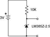
Set up the voltage standard using a precision voltage reference. You will need a breadboard, a zener diode (LM385Z-2.5), a 10K resistor, and a battery pack with two 1.5V batteries. Connect the voltage reference circuit as shown. Verify that the voltage is 2.5 V using a DMM. If it is not, see your instructor.
step 1. Calibrate the voltage divider. Connect the negative side of the voltage reference to near the negative end of your voltage divider using a test clip. Be sure to clip this near the negative end of the wire. Also be sure to position of the test clip so that its position can easily be measured using the scale on the meter stick. Now connect the positive output of the voltage reference to one of the DMMs (in voltmeter mode) and the DMM to the wire using a second test clip. Slide the test clip along until the wire until the DMM reads zero on the most sensitive voltage scale. Record the position of both test clips. Calculate the voltage gradient on the wire (Volts/cm).
step 2. Measure your VS. Repeat the procedure you used to calibrate the voltage divider, except substitute your VS for the voltage standard. In the calibration step the voltage was known but the voltage gradient was not. Now that you have measured the voltage gradient you can reverse the process to calculate the unknown voltage. Calculate the voltage of your VS.
step 3. Measure the resistance of the VS. Start from the same set up you just used to measure the voltage of the VS. Connect a standard resistor (~1M) across the terminals of the VS and re-measure the voltage using the voltage divider. Draw a schematic of your set up showing the resistances for VS and the standard resistor. From your schematic, derive the equation showing the voltage across the standard resistor at the null point. What current is being supplied by the VS? Given the voltage across the standard resistor, find the equation for the internal resistance Rs. Now calculate the short circuit current you would predict if the terminals of the black box were shorted together. (Do not actually short the VS.)
step 4. Measure the resistance of the DMM and the scope. Re-measure the voltage of your VS using the DMM and the scope. Draw a schematic of your set up showing the internal resistances of the VS and the voltmeter and the scope. (One schematic will suffice for both.) From your schematic, derive the equation for the internal resistance of the meters. Calculate the resistance of the DMM and the scope.
Null Point Measurement Lab: Lab Report Check List
Part 0. 2pts) Indicate the box number of your VS.
Part
1. 5pts) Quick survey
Your notebook should contain a diagram of your black box.
Label each terminal either + (positive), − (negative), or NC (no connection). Record
the voltages measured by the DMM and the scope.
Part
2. 4pts) Make the voltage divider and set up your standard
In you notebook draw a diagram of the voltage standard connected to your
voltage divider.
Record the voltage of your standard that you measure with the DMM.
Step
1 5pts) Calibrate the voltage divider
Record the position of the clips that connect the power supply to the
voltage divider. (Do not move these clips for the remainder of your
measurements!)
Record the position of both clips when the null point is achieved. Calculate
the voltage gradient in units of V/cm.
Step 2 5pts) Measure your VS. Calculate the voltage of the VS using your calibration.
Step
3 17pts) Measure the resistance of your VS.
Draw a diagram of the VS (with the 1M resistor) connected to your voltage. Record
the position of the clips at the null point.
Calculate the voltage you measured.
Draw a schematic of this setup. (Hint: The meter and the voltage divider do
not need to be included. Why?)
Write the equation for the voltage across the 1M resistor in this situation. Your
equation should include VS, RS, R(1M),
and V (your measurement).
Calculate RS by substituting into these equations.
Now calculate the short circuit current of the VS.
Step
4. 12pts) Measure the resistance of the DMM and of the scope.
Draw a schematic showing the resistance of the source and the meter.
Write the equation for the voltage across the voltmeter (Vm)
in terms of VS, RS, and RM.
Solve for RM by substituting into these equations.
