Lab 2: Voltage Dividers
In this lab you will build 3 different voltage divider circuits and explore their behavior.
In order to do this lab you need to understand the characteristics of resistors, potentiometers (pots), voltmeters, and power supplies.
Reading Ch 2.19 and 3.51 + lecture notes.
Components:
one 1 K trim pot, three resistors (1 K, 3.3 K, and 6.8 K), power supply, DMM,
an adjustment tool, a solderless bread board, cables, and wire.
Throughout this lab you will measure resistances and voltages with your DMM.

Potentiometer (AKA pot)
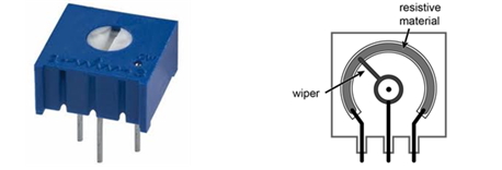
The potentiometer is a resistor with a third contact (arrow), which is internally connected to a wiper (sliding contact) that slides along the resistance material. The wiper position is controlled by a knob that adjusts the wiper position from one end of the resistor to the other. The wiper contact effectively divides the resistor into two resistors. For the purpose of analyzing a circuit containing a potentiometer, we include each of these resistors with the constraint that their series resistance is constant. We include the adjustability in the parameter x, which divides R into two resistors of values xR and (1−x)R. The end position of the wiper when turned fully clock-wise is often denoted on the pot with cw by that fixed end terminal.
A trim pot is designed to be used on the circuit board to make adjustments in the circuit, which once made are not performed routinely. A panel pot usually has a shaft with a knob and is designed for routine use, for example a volume control on a radio. In this class we will use trim pots because they are small and conveniently fit into our bread boards.
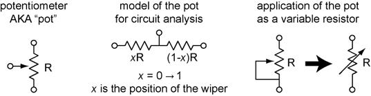
Variable resistor application: If a simple variable resistor (two terminals) is desired, the wiper is connected to one of the end terminals, shorting one of the ‘resistors’. Adjustability is commonly designated in schematic symbols by an arrow placed through the symbol at an angle. Although we could achieve the same function using one end terminal and the wiper only, there is an important practical consideration. In this latter design, an open circuit could occur if the wiper loses contact to the resistive material, e.g if the wiper bounces or breaks. Connecting the wiper to one end terminal prevents the variable resister from appearing as an open circuit, but will be limited to a maximum resistance of R if the wiper loses contact.
PART 1) The Potentiometer Obtain a 1 K trim pot and an adjustment tool. Using your DMM, measure the resistance across the end terminals of the pot, RAC. Construct a table in your notebook and record your measurements there.
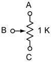
Q 1) 1pt. Does rotating the wiper change RAC? By how much does it change? If so, does it depend on the position or the motion of the wiper?
Now measure the resistance RAB and RBC with the wiper fully counterclockwise, approximately half way, and fully clockwise (total of 9 measurements). Note, you should always use the most sensitive scale for your measurement that still keeps the reading in the range.
|
|
Resistance |
||
|
fully CCW |
mid way |
fully CW |
|
|
RAC |
|
|
|
|
RAB |
|
|
|
|
RBC |
|
|
|

Table 1) 3pts. Construct and complete the table in your notebook.
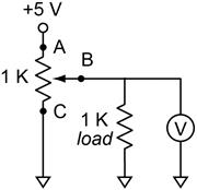
PART 2) The Potentiometer as a Voltage Divider. Build the simple voltage divider circuit using your bread board and the 5 V section of your bench-top power supply. Connect the output of the voltage divider to your DMM so that the voltage output can be measured. Before you connect the power supply, use your DMM to verify the voltage output is approximately 5 V. AND verify that you are connecting the power supply to the end terminals of the trim pot!
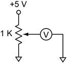
Turn on the power supply. The output of the voltage divider should vary smoothly from zero to the voltage of the power supply.
PART 3) Source Resistance of a Voltage Divider. Use the voltage divider you constructed in part 2 as a voltage source. A 1 K resistor will be the load. You will calculate the source resistance for the five different output voltages using your measurements of resistance and voltage. Construct a table in your notebook to do this. At each output voltage, 1) measure the open circuit voltage from the voltage divider (1 K load not connected) and 2) the voltage output after connecting to the load (do not readjust the wiper). Then carefully remove the trim pot form the circuit without moving the wiper and 3) measure the two resistances of the pot, the resistances from each end terminal to the wiper. Note that removing the trim pot from the breadboard is not actually necessary to measure the resistance of the pot.
Measure Vin and the 1 K resistor. Write these values in your notebook. You will need them for your Rsource calculations.
|
|
Voltage |
Resistance |
Rsource |
Rsource |
||
|
VOC |
Vload |
RAB |
RBC |
|||
|
max |
|
|
|
|
|
|
|
~4 V |
|
|
|
|
|
|
|
~3 V |
|
|
|
|
|
|
|
~2 V |
|
|
|
|
|
|
|
~1 V |
|
|
|
|
|
|

Table 2) 15pts. Construct and complete the table in your notebook.
Q 2) 8pts total. 4pts) Show the derivation of the source resistance of the voltage divider from RAB and RBC. 1pt) At what position of the wiper will the voltage divider have the maximum source resistance? 1pt) At what position of the wiper will the voltage divider have the minimum source resistance? 2pts) Show a sample calculation of Rsource using the equation you derived for your table above. Your sample calculation should show the algebraic equation, substitution of your numerical values into the equation, and the numerical result.
Q 3) 6pts total. 4pts) Show the derivation of the source resistance of the voltage divider from VOC and Vload. 2pts) Show a sample calculation of Rsource using the equation you derived for your table above. Your sample calculation should show the algebraic equation, substitution of your numerical values into the equation, and the numerical result.
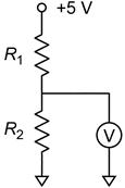
PART 4) Fixed Voltage Divider. Construct a fixed voltage divider using 3.3 K and 6.8 K resistors to provide ~ 3.3 V source. Measure the resistance of each resistor. Measure the output of the VD source.
|
measurements |
Vout calc. from measured resistances |
|||
|
Resistance |
Voltage |
|||
|
R1 |
R2 |
Vin |
Vout |
|
|
|
|
|
|
|
Table 3) 2pts. Construct and complete the table in your notebook.
Q 4) 2pts. Show a sample calculation of Vout using the voltage divider equation with R1, R2, and Vin. Your sample calculation should show the algebraic equation, substitution of your numerical values into the equation, and the numerical result.
Q 5) 2pts. You are using 5% tolerance resistors. Based on the tolerance and the nominal values of the resistors, what would be the maximum and the minimum voltage output you would expect selecting random resistors from the 3.3 K and 6.8 K drawers?
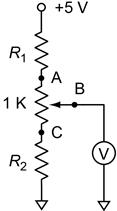
PART 5) A Narrow Range Adjustable Voltage Divider. You want a more precise 3.3 V source. Although you can achieve this by using the pot as in part 1, most of the adjustment range is wasted. Only a small range of the adjustment would be anywhere close to 3.3 V, so setting it exactly would be tricky. In practice it is better to use fixed resistors to get you close and then use a pot for the fine tuning. The resistance of the pot, in conjunction with the fixed resistors, will determine the adjustment range. Build this improved circuit from your fixed voltage divider (part 4) by adding your 1 K trim pot.
Measure Vin and the 3.3 K and 6.8 K resistors. Record these values in the columns in the table. They should be constants for all three sets of measurements.
|
|
|
Voltage |
Vout calc. from measured resistances |
||||
|
R1 |
R2 |
pot RAB |
pot RBC |
Vin |
Vout |
||
|
at Vout = 3.3 V |
|
|
|
|
|
|
|
|
at Vout = min |
|
|
|
|
|
|
|
|
at Vout = max |
|
|
|
|
|
|
|

Table 4) 9pts. Construct and complete the table in your notebook.
Q 6) 2pts. Show a sample calculation of Vout using the voltage divider equation with R1, R2, RAB, RBC, and Vin. Your sample calculation should show the algebraic equation, substitution of your numerical values into the equation, and the numerical result.
